Configuration |
MHARNESS allows users to configure the cable harness prior to simulation.
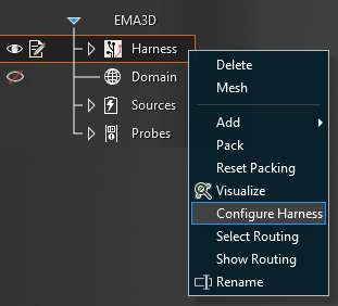
After the harness has been created and before the simulation is started, right click Harness in the Simulation Tree. Select Configure Harness from the pop-up menu.
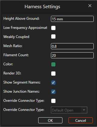
A new window will appear with the editable configuration settings. Hover over a property to view its description (also provided in the following table).
Setting | Meaning |
|---|---|
Height Above Ground [mm] | Ground plane offset (i.e., how far above the ground plane the harness is simulated). Only relevant to standalone MHARNESS simulations |
Low Frequency Approximation | When running an integrated MHARNESS/EMA3D simulation, a low frequency approximation is available that correctly couples the electromagnetic energy through the shields to the conductors within. This approximation is especially useful for low frequency phenomena such as lightning. Check the box to use the approximation |
Weakly Coupled | If selected, the harness is only weakly coupled (i.e., 1 way coupling) to the EMA3D simulation such that EMA3D fields couple to the harness but the harness effects are not coupled back to the EMA3D environment |
Mesh Ratio | The mesh ratio is defined as the segment diameter divided by the mesh cell size. If the ratio is above the set threshold (default=80%), the harness segment expands symmetrically into more than one mesh cell |
Filament Count | The number of charge filaments (default=20) used to characterize the charge distribution on the various conductors within a cable segment to facilitate capacitance matrix computations (see here for more) |
Color | Harness display color |
Render 3D | Equivalent to Visualize in the Harness menu. Check the box to visualize the harness as 3D tubes to more accurately represent the true size of cables |
Show Segment Names | Check the box to show segment names (SEG# or custom) on the model |
Show Junction Names | Check the box to show junction names (J# or custom) on the model |
Override Connector Type | Check the box to activate the connector type menu and override the open or closed connector type default |
Override Connector Type | Select the connector types to use during simulation (see here for more) |
EMA3D - © 2026 EMA, Inc. Unauthorized use, distribution, or duplication is prohibited.