Circuit Termination |
MHARNESS allows for cables to be terminated using complex Nexxim circuits. Users can define or import these circuits directly into MHARNESS and run them integrated with the EMA3D/MHARNESS simulation. Note that nonlinear circuit components connected to more than one MHARNESS pin can lead to numerical instability.
This topic contains the following sections:
Prior to defining a circuit termination, the cabling within the segment should be completed. Users should not define an MHARNESS termination point at the same location as a circuit termination.
Click Circuit Termination
 within the Harness section under the MHARNESS tab in the Ribbon.
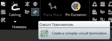
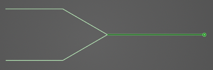
In the bottom left of the model window, the circuit termination instructions will appear asking the user to select a line at the end of which a circuit termination will be placed.
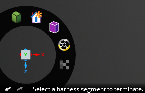
Using the cursor, select the line at the end of which the circuit termination will be placed. Hovering above the line will highlight it. The color of the line will not change when selected.
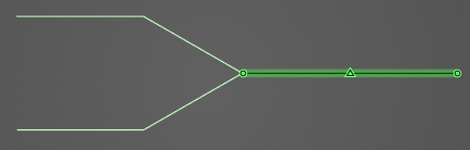
In the bottom left of the model window, the circuit termination instructions will ask the user to select the end point at which a circuit termination will be placed.
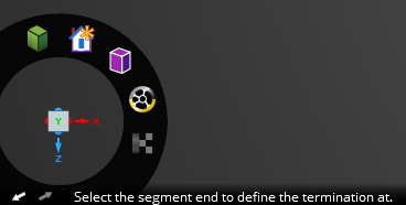
Using the cursor, select the end point at which the circuit termination will be placed. Hovering above the point will highlight both it and the previously-selected line. End points not connected to the previously-selected segment will not be selectable.
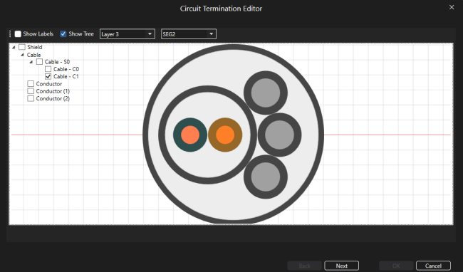
A new window containing the cable cross section will appear.
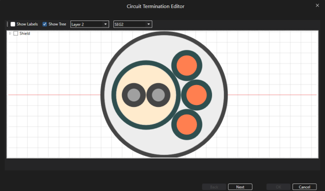
Select the cable(s) to which the circuit termination should be assigned. It will glow orange once selected. Users may need to use the drop-down menu at the top of the cross section window to change between cable layers. Once selected, click Next.
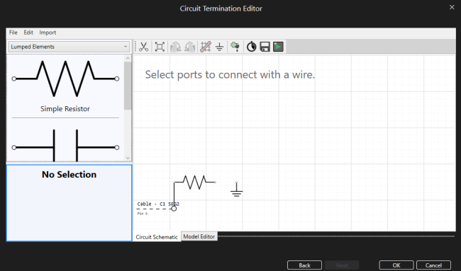
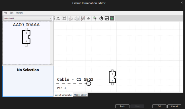
A new window will appear with the circuit termination builder.
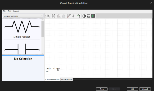
Use the tools to build the circuit termination. Double click circuit elements to add them to the model window. Be sure to use the connector tool to connect different elements - elements that are directly touching are NOT connected unless a wire connector is placed between them. Users may need to zoom out or use the zoom all button to view all available cable pins. Click the Escape key to exit a tool.
Click OK to complete the setup.
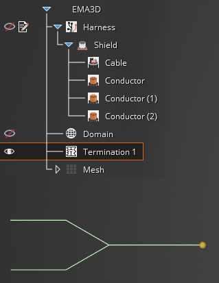
The end point with the circuit termination will be recolored cyan in the model window. Users may need to hide the junction point labels to see the circuit termination.

The circuit termination will be added to the Simulation Tree as
 Termination #.
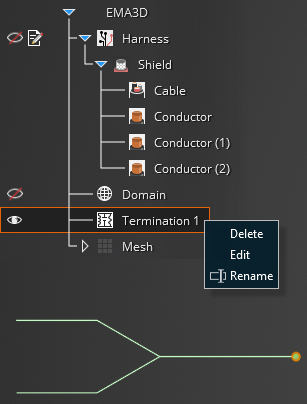
Users can delete, edit, and rename circuit terminations in the Simulation Tree by right clicking them.
Users can save the circuit schematic as an .xml file to be loaded in later by selecting File > Save from the circuit termination GUI ribbon. To load this schematic in, select File > Open.
Button | Meaning |
|---|---|
| Delete the selected component (alternatively, if component is selected press the delete key) |
| Zoom to fit all components |
| Rotate the selected component 90 degrees clockwise (alternatively, if component is selected press the R key) |
| Rotate the selected component 90 degrees counter-clockwise |
| Tool to connect ports/pins/elements together (all components MUST be connected using this tool) |
| Add a ground to the circuit |
| Add a voltage probe to the circuit |
| Add a current probe to the circuit |
| Add a pin to the circuit (only use if running a standalone simulation, otherwise add pins using the methodology from Section 1) |
| Adjust the stop time and time step of a standalone simulation (running an integrated MHARNESS/EMA3D simulation overrides these time properties) |
| Adjust various tolerances and other Nexxim settings |
| Save the netlist .nci input file to run a standalone simulation later |
| Run a standalone simulation from the netlist .nci input file |


It is possible to test circuit terminations prior to running them as part of the integrated MHARNESS/EMA3D simulation by running them standalone from the circuit termination GUI.
Follow the steps in the previous section to create the circuit. In standalone circuit termination simulations, all input from the pins is zero. Therefore, sources should be added to the circuit prior to simulating.
In integrated simulations, the time settings are imported from MHARNESS/EMA3D. In standalone simulations, users must input the stop time and time step (the start time is 0s by default). Click
 Time in the circuit termination GUI to set the stop time and step time.
Next, users must save the .nci input file containing all of the necessary properties for the simulation. Click
 Save in the circuit termination window.
Click
 Play in the circuit termination window. Select the previously-exported .nci input file from the pop-up window.
A progress bar will appear.
Once complete, the simulation output can be found in the .csv file in the same directory where the .nci input file was saved. Users can plot the fields using any external plotting software.
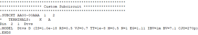
It is possible to import subcircuit elements to use in a custom circuit termination.
Before beginning, the .txt file containing the subcircuit information should follow a similar format to the following:
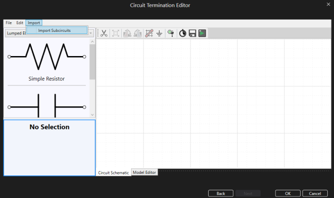
Select the Import button from the circuit termination GUI ribbon. Then select Import Subcircuits.
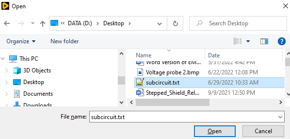
In the pop-up window, select the .txt file containing the subcircuit information. Click Open.
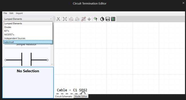
The imported subcircuit can be found in the dropdown menu on the left-hand side of the circuit termination GUI.
Select the subcircuit from the drop-down menu. A graphic of the subcircuit will appear with labels (obtained from the .txt file) at each port.
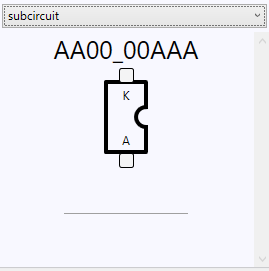
Double click the graphic of the subcircuit to add it to the circuit termination.
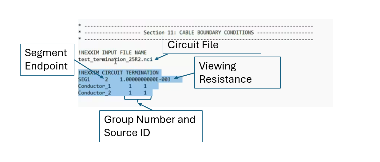
When analyzing the .nci file, we can also input our desired properties for the simulation by editing the file's inputs
EMA3D - © 2026 EMA, Inc. Unauthorized use, distribution, or duplication is prohibited.