Harness |
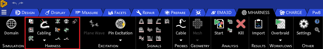
The Harness section contains tools used to define the cabling within the MHARNESS model. The configuration of the harness parameters can be adjusted prior to runtime, as discussed on the Configuration page.
The Harness section has the following tools:


Harness also has several tools (described in the table below) that can be accessed by right clicking  Harness in the Simulation Tree.
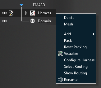
Tool | Function |
|---|---|
| Deletes the entire harness |
| Renames the harness |
Mesh | Mesh all lines in the harness |
Add | Add cabling to the harness |
| Packs (i.e., arranges the cables in the harness such that there are no overlaps) all cables in harness but retains all user-defined cross sections |
| Clears the user-defined cross sections and repacks cables using the default packing algorithm |
Visualize | Visualize the harness as 3D tubes to more accurately represent the true size of cables |
| Open the menu to configure harness properties |
Select Routing | Highlight and activate the line(s) in the model geometry that comprise the harness |
Show Routing | Hide all geometry except for the line(s) in the model geometry that comprise the harness |


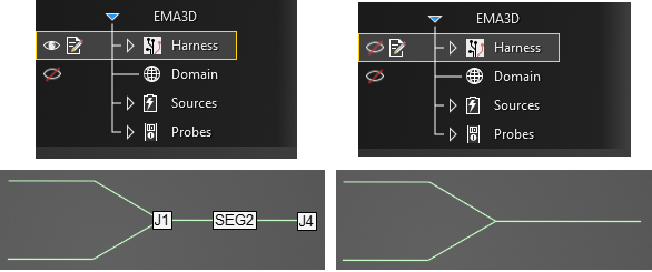
In addition to the above tools, there are a few quality of life harness tools users can access.
Hide Junction and Segment names by unchecking the box next to the
Harness node in the Simulation Tree.
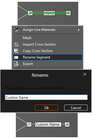
Rename segments by right clicking the line segment in the model window and selecting
 Rename Segment from the pop-up menu.
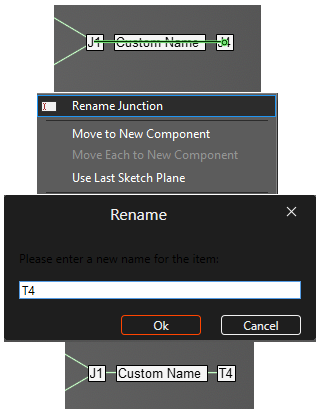
Rename junctions / terminations by right clicking the junction point in the model window and selecting
Rename Junction from the pop-up menu.
EMA3D - © 2026 EMA, Inc. Unauthorized use, distribution, or duplication is prohibited.