Mesh |
When meshing the model geometry, it is important to mesh all relevant geometric entities – bodies, surfaces, lines, and points. Failure to do so may result in some unintended consequences. For example, if only a surface was meshed, then only the nodes associated with the surface would be generated and only the finite difference model associated with the meshed surface would be defined. However, the line may provide a necessary connection, perhaps a conductive path, and therefore the nodes associated with the meshed line may be important.
When the geometry has been meshed, it should be examined to see if the resultant meshed structure is acceptable to within the bounds of the required numerical objectives. Mechanisms affording coupling from one region to another, such as apertures and narrow passages, should be inspected. Thin wires or cables running through narrow passages can often be meshed into the surrounding material and unintentionally bonded or grounded causing confusing wire or cable responses. To make inspection easier, recall that the material color format is A, R, G, B and choosing an A between 0 (most transparent) and 255 (opaque) can make the color and mesh semi-transparent.
The steps for meshing are outlined below. The mesh tool automatically meshes all entities within the largest domain. The steps to mesh only certain entities are also outlined below. Use the links to jump to a specific section:
In order to mesh a structure, it must have a material assigned to it and be contained within the lattice.
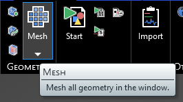
Click Mesh
 under either the MHARNESS or EMA3D tab in the Ribbon. The amount of time it takes to complete the meshing will depend on the size of the model, size of the mesh, and the computer.
The model will appear meshed. If the Definitions node is selected in the Simulation Tree, the mesh will be colored by material.
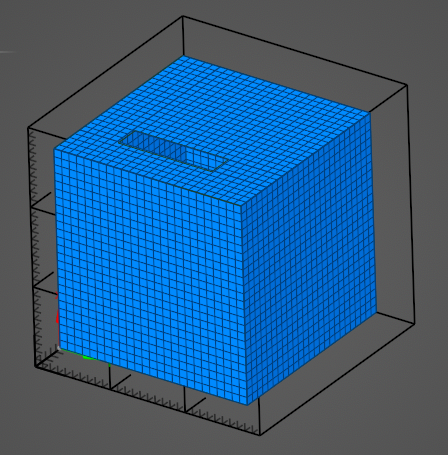
To better visualize the mesh, click in a blank area of the model window and select Inverse Visibility in the pop-up menu. Alternatively, in the Structures Panel, deselect some of the model components to increase mesh visibility.
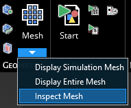
Below the mesh button, there are several options:
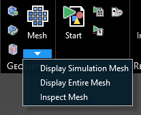
Display Simulation Mesh shows all mesh that will be used in the simulation.
Display Entire Mesh shows all mesh regardless of whether it will be used in the simulation.
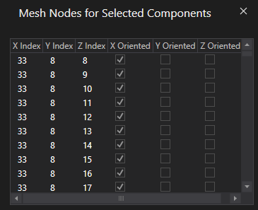
Inspect Mesh allows the user to select individual geometry to more closely examine the mesh. Selecting an item will show the mesh of only that element but in the properties panel the individual mesh coordinates of each cell will be shown. Hold down ctrl on the keyboard to select multiple items to inspect.
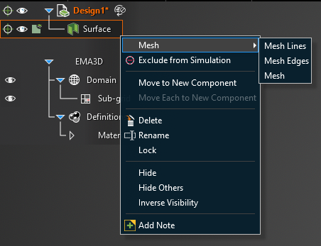
To mesh just one entity, such as a line or a surface, right click the entity in the structure tree and click Mesh. Then select which parts of the entity to mesh.
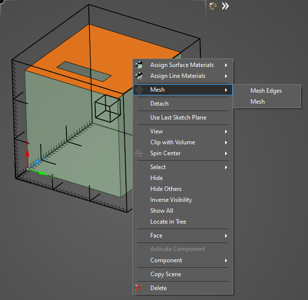
Alternatively, select the entity in the model window. In the pop-up window, select Mesh and then select which parts of the entity to mesh.
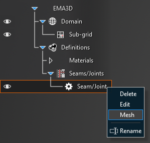
To mesh a Seam/Joint, right click the Seam/Joint in the Simulation Tree and click Mesh. Seams should be visually inspected to ensure they are continuous. If the mesh of the seam is discontinuous, then the seam is “leaky” and current will travel through the leak unimpeded by the seam. Leaky seams most often require geometric modifications to fix. Seams that are not parallel to the coordinate axes typically receive a “stair step” mesh which can sometimes produce leaky seams.
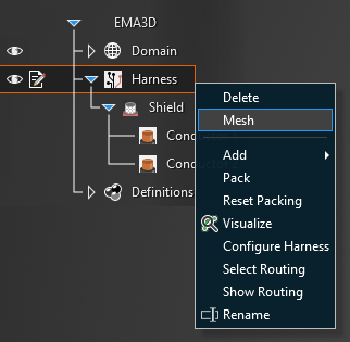
To mesh the entire harness, right click Harness in the Simulation Tree and click Mesh. EMA3D has various deconfliction algorithms for the harness, which are discussed on the Settings page.
Click the drop-down arrow beneath the Mesh
button. Then select Inspect Mesh.
In the top left of the model window, several selection tools will appear. Choose the appropriate selection tool (body
 , surface
  , line
  , or point
  ) for the geometry to be inspected.
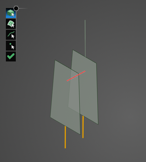
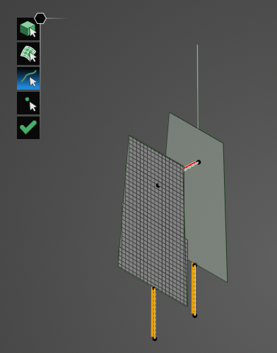
Click on geometry in the model to view its mesh. Hold down the CTRL key while selecting to view the mesh of several items at once. To switch selection tool types while maintaining the current mesh, release the CTRL key, select the new tool, and then hold CTRL again while making a new selection on the model.
Click OK
 to close the tool.
Click the drop-down arrow beneath the Mesh
button. Then select Edit Surface/Body Mesh.
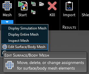
Several directional arrows will appear in the model window. Drag the bounds of the directional arrow box to encompass the mesh that is to be altered. The selected mesh cells will turn yellow.
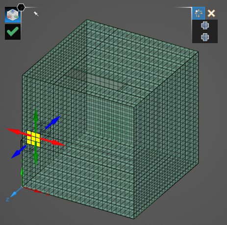
To the top right of the model, select either Move or Delete.
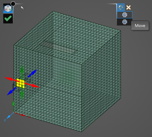
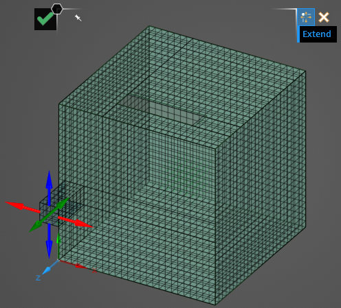
If Move is selected, a new set of directional arrows will replace the existing set and the selected mesh cells will no longer be highlighted. Use the directional arrows to drag the mesh. If Extend is set to True (blue), the mesh will maintain connectivity, if Extend is set to False (white) the mesh will move without maintaining connectivity.
Click OK
to complete the mesh editing. Then click OK again to close the tool and save the new mesh.
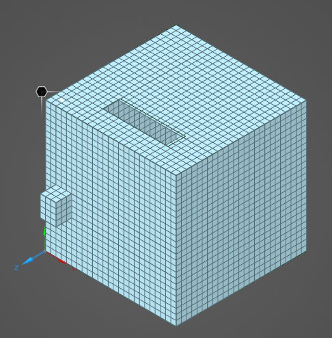
If Delete is selected, the selected yellow cells will be immediately deleted.
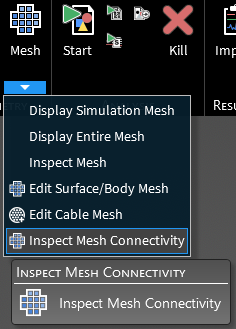
After the geometry has been meshed, click the drop-down arrow beneath the Mesh
button. Then select Inspect Mesh Connectivity.
The
Select Surface tool will appear in the model window.
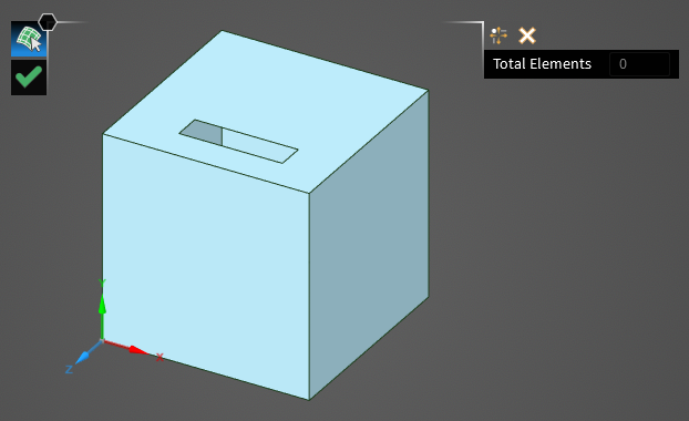
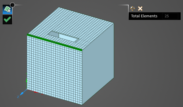
Select the two surfaces between which the mesh connectivity should be checked. The mesh will appear when each surface is clicked. A green line will appear where the mesh of the two surfaces are touching. Additionally, to the top right of the geometry, the total number of mesh elements between the surfaces that are connected to one another will appear.
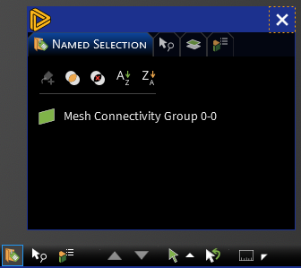
Click OK
to complete the mesh connectivity inspection. A new group containing the mesh connectivity of the selected surfaces will appear in the Named Selection section of the GUI located in the bottom right of the model window.
There are two options in the general settings menu: Improved Surface Connectivity (enabled by default) and Surface Interface Smoothing (disabled by default).
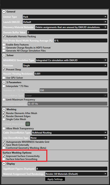
Improved Surface Connectivity provides surface level post-processing for surface meshing that improves connectivity within meshed surfaces by reduing the occurence of gaps and misaligned surface alignments.
These undesireable features occur from ambiguous states that result when CAD geometry passes through the center of cells in the lattice. The post-processor adopts a rounding convention, as well as hole- and alignment-fixing algorithms to produce higher quality surface meshes.
Note: Though connectivity is improved within each individual surface, connectivity at the interfaces of separate surfaces is not addressed by this feature and could change as compared to legacy behavior. Users should check their meshes to ensure that connectivity between surfaces is acceptable. This feature can be disabled to return to legacy surface meshing behavio by unchecking the "Improved Surface Connectivity" box.
Additionally, this update can be appied selectively to different surfaces by the following procedure: users can mesh surface,s change the meshing option in the setting menu, and then right click on the surface selecting mesh to re-mesh the individual surface with hte new mesh settings. This allows for selectively meshing surfaces with the options that are best for that surface.
When the options box is hovered over, the following text is displayed: "Post process surface elements to ensure local surface connectivity (re-mesh required for setings to apply)."
Surface Interface Smoothing is a global post-processor for reducing undesireable overhanging surface elements caused by the intersection of meshed elements of two surface facets sharing an edge. The algorithm operates by flagging cells surrounding facet edges, and tries to reduce the number of boundary and overshared edges by removing spurious surface elements while preserving connectivity.
Note: While the algorithm improves surface mesh quality in many cases, performance may vary from model to model. The user should always visually inspect their mesh to ensure compliance with their requirements. This feature can be enabled by checking the "surface Interface Smooothing" box.
When the options box is hovered over, the following text is displayed: "Smooth meshed boundary of coincident surfaces by removing overhanging surface elements (re-mesh required for settings to apply)." This option can be enalbed/disabled for surfaces as described for "Improved Surface Connecctivity".
Other Resources
EMA3D - © 2026 EMA, Inc. Unauthorized use, distribution, or duplication is prohibited.