Visualize |
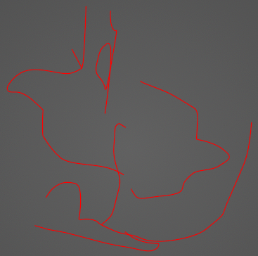
The Visualize tool changes the model window representation of the harness from lines to 3D tubes. This change allows users to see the cross-sectional width of the wires relative to the size of the other geometry and other wires, rather than only seeing the same size line representation for both.
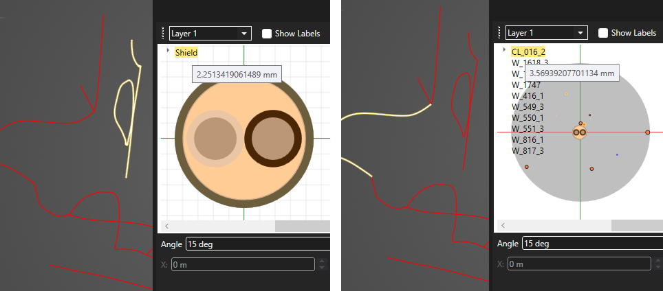
Two cable segments within the Harness below have the following cross sections. The difference in radius between the two segments is approximately 1.3 mm, but both are represented by the same thin line in the model window. Visualizing the harness will allow users to see how the two compare in the geometric problem space.
To visualize the harness:
Select the Visualize
 tool from the Harness section within the MHARNESS tab of the ribbon.
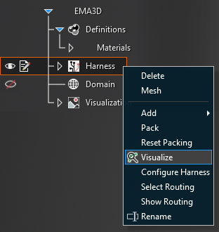
Alternatively, right click Harness in the Simulation Tree and select
Visualize from the pop-up menu.
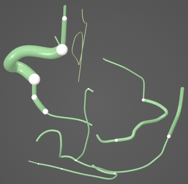
The harness will now appear in the model window as a series of tubes that are scaled to show the harness size relative to other geometry and other harness segments. The white spheres indicate the meeting point of two harness segments (the spheres are not necessarily junctions as defined for the purpose of MHARNESS physics).
Press the Esc key to exit the Visualization tool and return to normal view.
EMA3D - © 2026 EMA, Inc. Unauthorized use, distribution, or duplication is prohibited.