Copy Cross Section |
The Copy Cross Section tool allows the user to apply a desired cable cross section, complete with adjustments to interior cable spacing and location, to other cables. The cross section can be copied to previously-defined cables, which will overwrite their current configuration, or to undefined lines in the model, which will create a new harness segment. This tool is especially useful when twisting cables.
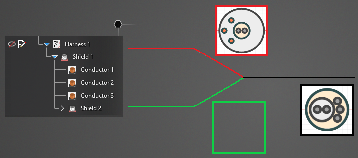
Note that the harness segments TO which the cross sections are copied will become part of the cable FROM which the cross section was copied (e.g., copying the cross section of Shield_1 to line_segment will route Shield_1 through line_segment - it will not create an independent Shield_2).
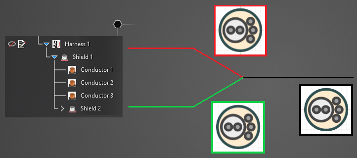
The model below has two harness segments defined. The two segments are made up of the same cables, as shown in the image of the Simulation Tree, but those cables' locations and spacing are different. Their cross sections are shown in red and black. The green segment has no cable defined.
To apply the cable cross section of the black segment to the red and green segments:
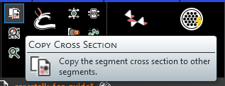
Select the Copy Cross Section
 tool from the Harness section within the MHARNESS tab of the ribbon.
Using the Select Line
 tool, select a harness section in the model window to copy its cross section. The segment will glow when hovered over and its cross section will be displayed.
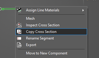
Alternatively, right click the black line segment in the model window and select
Copy Cross Section from the pop-up menu. This method automatically selects the right-clicked cross section as the cable cross section to be copied.
Once chosen using either method, the selected cable will highlight yellow in the model window.

Using the Select Line
tool, select the red and green line segments to copy the black cable's cross section to them. The segments will highlight blue to show that they are selected.

Click
 OK to finish apply the new cross section.
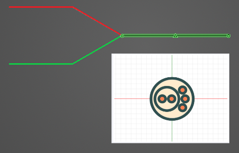
If desired, use the
 Inspect Cross Section tool to view the new cable cross sections.
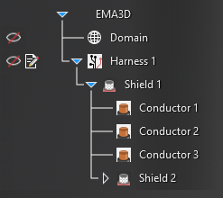
As noted in the introduction, notice that only the Shield and its interior components exist in the Simulation Tree, which indicates that all of the cable segments in the model are part of Shield.
EMA3D - © 2026 EMA, Inc. Unauthorized use, distribution, or duplication is prohibited.