Port |
Ports are used to specify the location and reference impedance of individual ports in an S-parameter network. Details on running an S-parameter simulation can be found here. It is important to note that EMA3D and MHARNESS runs separate simulations for each defined port.
Prior to defining a port, the cabling within the segment should be completed. Ports should not have defined termination points, as that would define the reference impedance twice.
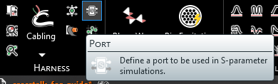
Click Port
 within the Harness section under the MHARNESS tab in the Ribbon.
In the top left of the model window, the port definition tools will appear.
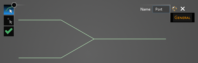
Using the Select Line
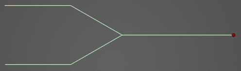
 tool, select the line at the end of which the port will be placed. Hovering above the line will highlight it. The color of the line will not change when selected.
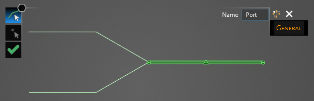
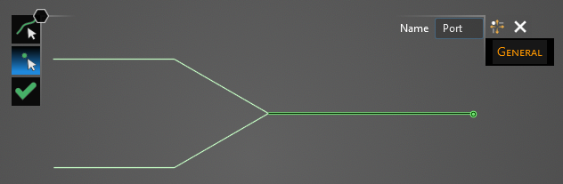
Using the Select Point
 tool, select the end point at which the port will be placed. Hovering above the point will highlight both it and the previously-selected line. End points not connected to the previously-selected segment will not be selectable.
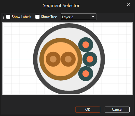
A new window containing the cable cross section will appear.
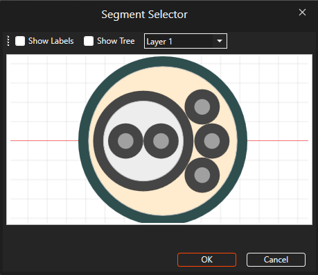
Select the cable to which the port should be assigned. It will glow orange once selected. Users may need to use the drop-down menu at the top of the cross section window to change between cable layers. Once selected, click OK to complete the port setup.
The end point with the port will be recolored red in the model window. Users may need to hide the junction point labels to see the port.
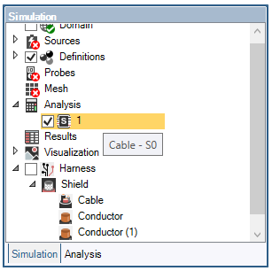
The port will be added to the Simulation Tree under the Analysis node as
 #. Users can also hover over the port in the Simulation Tree to see the cable to which it is assigned.
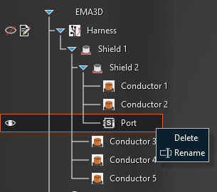
Users can delete and rename ports in the Simulation Tree by right clicking them. Ports are not currently editable. To change a port, users will need to right click it in the Simulation Tree and click
 Delete. Users can then repeat the above steps to create a new port.
EMA3D - © 2026 EMA, Inc. Unauthorized use, distribution, or duplication is prohibited.