Terminations |
Four different cable termination types exist in MHARNESS. Users may choose between them within the properties panel after assigning termination points. Cables with multiple layers can have different termination types for each cable, if applicable.
This page contains information on the following:
This topic contains the following sections:
Surrounding Material
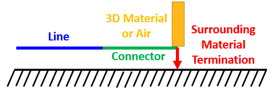
Users should only apply to the end of the outermost conductors (conductors with 3D material as their reference)
The cable is terminated into the 3D material that surrounds the termination
The surrounding material may be air or a 3D surface/body with a finite conductance
If applied to a shield, the coupling inside of the shield depends on the type of material into which the cable is terminated
Boundary
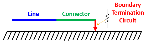
Boundary conditions may be applied to the end of any conductor, whether it is the outermost or a shielded conductor
The boundary condition applies an additional circuit termination between the conductor and its reference (see: Boundary Condition Circuit Types)
The boundary circuit may be a linear combination of resistors, inductors, or capacitors
During normal simulations (open conditions), If the impedance is high enough on the end of a shield, additional fields may couple to the interior of the shield
During S-Parameter simulations (closed conditions), coupling to the interior of a shield does not depend on the boundary impedance
Impedance Match
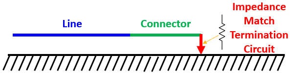
Impedance match may be applied to the end of any conductor or shield
Impedance match is applied in a similar manner to the boundary condition
The impedance applied between the end of the conductor or shield and the reference is automatically set to remove all reflections at the termination interface
Conductance
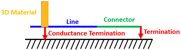
Conductance terminations may be applied to an interior division of a shielded conductor or interior shield as it passes through a bulkhead
The conductance termination specifies that the conductor is in contact with the bulkhead as the termination location
If any conductor or shield has a conductance specified, all the other conductors or shields at the same system level without a conductance termination are isolated from the bulkhead
This allows users to specify the conductors or shields that are bonded to the bulkhead and those that are allowed to pass through unbonded
A common use is to allow interior twisted pair shields to ground at a bulkhead connector while the twisted pair conductors continue through the connector without an electrical connection
An example termination set is given below. An overbraid contains three TSPs routed through several bulkheads.
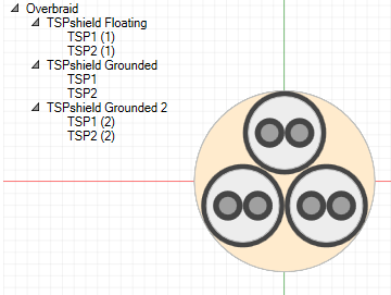
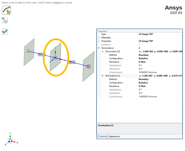
One of the TSP shields is not grounded to the middle bulkhead and so only has Boundary type boundary conditions at the first and third bulkhead and no termination at the middle bulkhead. Like the shield, the twisted pair conductors continue through the bulkhead without an electrical connection.
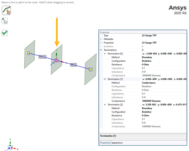
Two of the TSP shields are grounded at the middle bulkhead and so have Boundary type boundary conditions at the first and third bulkhead and a Conductance type termination at the middle bulkhead. Unlike the shields, the twisted pair conductors continue through the bulkhead without an electrical connection.
The following examples show how to pass cables through surfaces with different types of electrical connections.
Electrical Pass Through
No junction at the location the cable passes through the surface (junctions automatically bond the outermost cable layer to the surface)
Outermost conductors or shields in the cable should have a dielectric jacket
Conductors or shields will have no electrical connection to the surface, provided that the cable mesh is orthogonal to the surface mesh with no overlapping cells
No need for users to create an opening in the surface
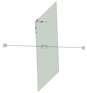
Electrical Connection of Outermost Shield or Conductor
Place junction at the location the cable passes through the surface (junctions automatically bond the outermost cable layer to the surface)
Outermost conductors or shields will be electrically connected to the surface
Surrounding Material termination type can help the user to identify locations where electrical connections between harness and 3D material exist and is recommended at the junction (J2 in the figure)
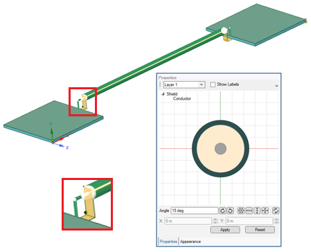
Electrical Connection of Inner Shield or Conductor
Inner conductors are isolated from the 3D material at junctions by default
The outermost shields will have an electrical connection to the surface (junctions automatically bond the outermost cable layer to the surface)
Inner conductors are continuous through the junction with no electrical connection
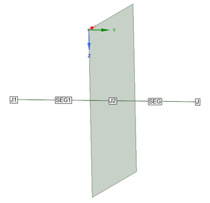
The following examples show how to break conductors outside of shields at either 3D surfaces or air.
At 3D surfaces
Conductors or shields that are inside of another shield may break outside of that shield
In the figure above, the coax shield terminates in the 3D surface while the coax inner conductor continues outside of the shield
This shield could have no terminations assigned or use Surrounding Materials termination to track the electrical connection points
This conductor should have no terminations assigned
In Air
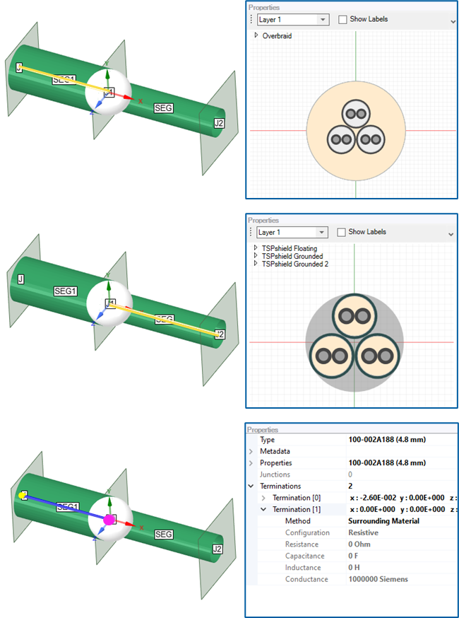
Conductors or shields that are inside of another shield may break outside of that shield
In the figure above, the overbraid shield ends with a Surrounding Material termination type (which is air in this case) while the three twisted, shielded pairs continue outside of the overbraid with no termination types assigned
MHARNESS cable terminations can have either open or closed terminations. The default behavior is Connector Type Open for normal simulations and Connector Type Closed for S-Parameter simulations.
Open Terminations
If the impedance is high enough on the end of a shield, additional fields may couple to the interior of the shield
EMA3D Cable gives the user the ability to allow this additional coupling into poorly-terminated cables via the open connector type
See here for more information
Closed Terminations
If users prefer the coupling through shields to be independent of the shield termination, the closed connector type should be selected
See here for more information
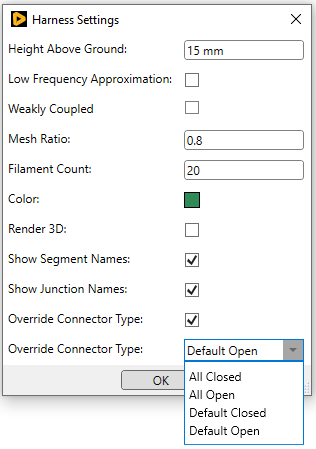
To override the default connector types:
Open the Harness Settings menu by right clicking
 Harness in the Simulation Tree.
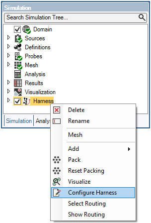
Check the box next to Override Connector Type then select the type in the dropdown menu beside Override Connector Type. As mentioned, the default behavior is Connector Type Open for normal simulation and Connector Type Closed for S-Parameter simulations. The default connector type is should be used for most simulations, however, a specific use case may call for the type to be overridden.
EMA3D - © 2026 EMA, Inc. Unauthorized use, distribution, or duplication is prohibited.