Connector Closed |
It is important to understand the concepts of a ‘closed’ and an ‘open’ connector. These concepts are enacted by various connector specifications and are depicted in Figure 5.5.1.1. A closed connector maintains the definition of a transmission line in the traditional sense, as seen in Figure 5.5.1.1(A). There is no inward coupling to conductors within a shield except by way of the transfer impedance. The shield is terminated to its reference and the inner conductors are likewise terminated to the shield. The conductance at the shield end, or the boundary conditions at the shield end, define only how the ends are connected to the associated reference.
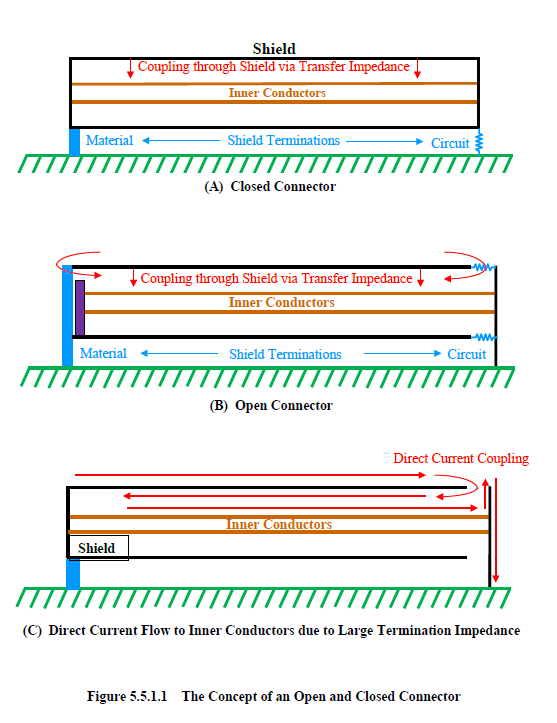
For an ‘open’ connector, on a shield, the terminations (material or circuit) create apertures at the ends allowing additional energy to couple to the interior as portrayed in Figure 5.5.1.1(B). If the termination specifications result in a high circuit resistance (or low material conductivity), then a direct current path is created from the shield to the inner conductors. For high resistances, the current will flow almost uninhibited from the shield to the inner conductors, as portrayed in Figure 5.5.1.1(C)
In reality, cable terminations are usually open (“Connector Open”). If a cable connector, or perhaps an overbraid, is connected to a bulkhead through a termination resistance, then the very nature of such a connection would allow the coupling of energy through the resistive termination to the inner conductors. If the resistance was large, then a significant amount of energy may be coupled. If the overbraid terminated in air, and the inner conductors grounded through a small resistance, then most of the current would couple to the inner conductors. A small amount, however, may be reflected at the open end. A connector, by default, is always “closed” unless it is specified to be “open”.
EMA3D - © 2026 EMA, Inc. Unauthorized use, distribution, or duplication is prohibited.