Pin Wire Connectors |
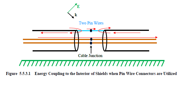
A pin wire connector on a shield modifies the shield at the connector to represent a wire that can then be directly connected to a connector pin. Such a configuration allows the division of current at the shield end to divide, as illustrated in Figure 5.5.3.1. Some of the current will flow to the inner conductors and some will flow along the pin wire. All pin wires must be connected to a junction. The drawing in the figure shows a pin wire on either side of a junction. It is not necessary to have two pin wires aligned in this fashion. Only one pin wire may be specified although it must be connected to a junction.
EMA3D - © 2026 EMA, Inc. Unauthorized use, distribution, or duplication is prohibited.