Cable Group |
A Cable Group allows users to bundle cables within the harness, twist the entire bundle of cables if desired, and apply padding around the group without having to use a shield. Cables within cable groups should all follow the same route and terminate at the same locations.
Please note, if twisted cables are desired, please see the Twisted Cables page prior to defining the cable.
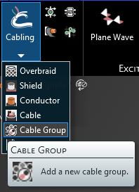
Click Cabling
 under MHARNESS in the Ribbon then select Cable Group.
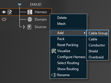
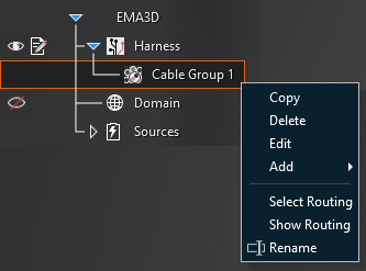
Alternatively, right click Harness in the Simulation Tree, then select Add in the pop-up menu, and finally select Cable Group.
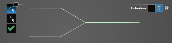
In the top left of the model window, the cable tools will appear.
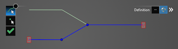
Using the Select Line
 tool, select the line segments that comprise the conductor by left clicking them individually or by
using the lasso function (hold down left mouse button and drag to fully encompass all line segments in the conductor, then release the mouse button).
The selected segments will turn blue and the line junctions will show as blue dots. The red, boxed U at each end point stands for unterminated endpoint.
tool, select the line segments that comprise the conductor by left clicking them individually or by
using the lasso function (hold down left mouse button and drag to fully encompass all line segments in the conductor, then release the mouse button).
The selected segments will turn blue and the line junctions will show as blue dots. The red, boxed U at each end point stands for unterminated endpoint.
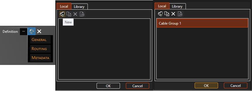
In the Properties Panel, click the ellipsis to the right of Definition. In the pop-up window, click New
 in the Local Tab. Select Cable Group.
Note when applying a cable group from the local tab that all cable groups defined with that specific cable name will share the same properties. To correctly identify each cable group in the Local Tab at a later time it is a good idea to rename the Short Name in the Metadata section of the Properties Panel when first assigning it.
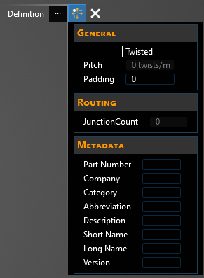
The properties of the cable group can be changed within the Properties Panel. Select a property to see its definition. A list of cable group properties and their definitions is provided at the bottom of this page. If cable twisting is desired, please see the next section of this page.
Click OK
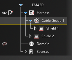
 to create the cable group. Cable Group will appear in the Simulation Tree nested within the Harness node.
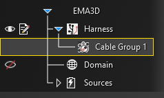
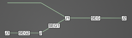
Additionally, the line in the model window will revert to its original color and it will have SEG and J labels on it indicating segments and junctions. Uncheck Harness in the Simulation Tree to hide these labels if desired.
To delete, rename, copy, or edit the cable group after it has been created, right click Cable Group in the Simulation Tree. Add will allow the user to define a new cable that is nested within the cable group (users should be careful to select the same route and termination locations for the nested wires as for the cable group). Select Routing highlights and activates the line(s) in the model geometry to which the cable group is assigned. Show Routing hides all geometry except for the line(s) in the model geometry to which the cable group is assigned.
Note that when editing a cable, any changes to the cable properties are applied immediately regardless of whether the OK
button is pressed. Changes made to the cable route, however, do not apply until OK is pressed; MHARNESS will show a warning if users try to exit without clicking OK .
This behavior is useful in conjunction with turning off Automatic Harness Packing in the MHARNESS settings because automatically repacking the harness each time a route change or cable property is changed can be time consuming for the MHARNESS software.
Users can also add cables to the cable group by selecting the cable in the Simulation Tree and dragging and dropping it on Cable Group. The selected cable will appear nested within Cable Group. Users should be careful to select the same route and termination locations for the nested wires as for the cable group.
To view a cross section of the cable group after it has been created, select the
 Inspect Cross Section tool from the Harness section within the MHARNESS tab of the ribbon and then hover over the conductor line. Alternatively, right click the line in the model window and select Inspect Cross Section from the pop-up menu to immediately enter the cross section editor. See the Inspect Cross Section page for more.
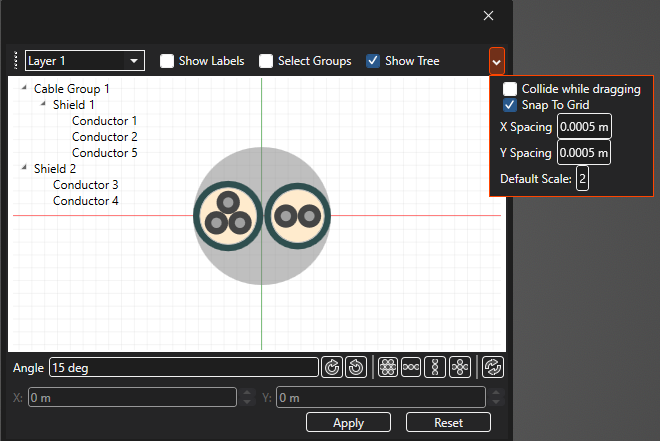
As there is no jacket component to a cable group, the cross section will be blank until wires are added to the cable group or unless padding has been applied. Once wires are nested within the cable group or padding has been applied, the circumference of the cable group plus its padding will be denoted by a gray circle (which is not a physical part of the cable group).
The placement and spacing of the cable(s) can be adjusted in the cross section editor by dragging and moving the cable(s) in the cross section or by using the tools located beneath the cross section. If the cable group has multiple layers, use the dropdown menu in the top left of the Properties Panel to move between layers. Other parameters can be found by clicking the small drop-down arrow in the top right of the Properties Panel window. Note that Default Scale changes only the view scale (1 shows the cross section at full scale, 2 is half scale, etc.). Be sure to click "Apply" before closing the window to save any changes.
Entry | Meaning |
|---|---|
Metadata | |
Short Name | The display name of the cable group in the local tab |
|
|
Properties | |
Twisted | If the contents of the cable group should be twisted select True, otherwise select False |
Pitch [Twists/m] | The twist rate of the cable group contents |
Padding [m] | Padding around the cable group |
|
|
Junctions | The number of junctions in the cable group route |
EMA3D - © 2026 EMA, Inc. Unauthorized use, distribution, or duplication is prohibited.