Cable |
In the frame of MHARNESS, a Cable is intended as a cable with a pre-defined topology. This feature allows users to insert cables as single elements without having to construct them from their constituent components each time. MHARNESS includes properties for a variety of common off-the-shelf cables including Coaxial, Twisted Shielded Pair (TSP), Twisted Shielded Triple (TST), and Twisted Shielded Quadrax (Quadrax) cables whose parameters were experimentally measured. MHARNESS also has a shield type called Singles, which is a single conductor with a shield around it. Unlike the Coax cable type, the singles shield type may not have a characteristic impedance of 50 ohm. This type of cable is commonly used for power and analog signals.
Please note, if twisted cables are desired, please see the Twisted Cables page prior to defining the cable.
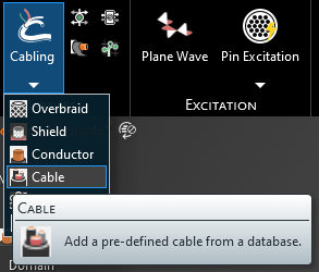
Click Cabling
 under MHARNESS in the Ribbon then select Cable.
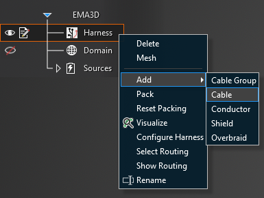
Alternatively, right click Harness in the Simulation Tree, then select Add in the pop-up menu, and finally select Cable.
In the top left of the model window, the cable tools will appear.
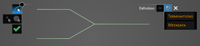
For Cable, the cable type must be selected before the route is defined. In the Properties Panel, click the Library button to the right of Definition. In the pop-up window, click the Library Tab, expand the desired shield categories, and finally select the cable type.
If the cable has been previously used in the project, the type can also be selected from the Local Tab, rather than the Library Tab. Note when applying a cable type from the local tab that all cables defined with that specific cable name will share the same properties. For instance, applying a 24 Gauge TSP from the library and then applying a second 24 Gauge TSP from the library produces two separate TSPs in the Local Tab with independent properties. Alternatively, if a 24 Gauge TSP is applied from the library and then is later selected and applied from the Local Tab, all of those TSPs share the same properties. Think of the library as a set of generic wires and the Local Tab as a set of specific wires. To correctly identify each cable in the Local Tab at a later time it is a good idea to rename the Short Name in the Metadata section of the Properties Panel when first assigning cables.

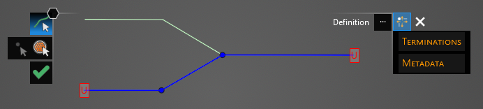
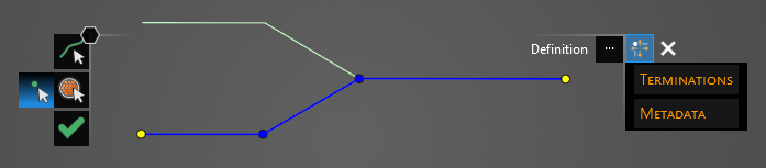
Using the Select Line
 tool, select the line segments that comprise the cable by left clicking them individually or by
using the lasso function (hold down left mouse button and drag to fully encompass all line segments in the cable, then release the mouse button).
The selected segments will turn blue and the line junctions will show as blue dots. The red, boxed U at each end point stands for unterminated endpoint.
tool, select the line segments that comprise the cable by left clicking them individually or by
using the lasso function (hold down left mouse button and drag to fully encompass all line segments in the cable, then release the mouse button).
The selected segments will turn blue and the line junctions will show as blue dots. The red, boxed U at each end point stands for unterminated endpoint.
Because there are generally multiple nested cables when using the Cable tool, the terminations are configured separately for each cable. There are two options for choosing which cable terminations to configure:
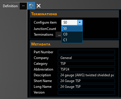
In the Properties Panel, select Configure Item and then click the drop-down arrow in the box to its right. Select the cable on which to configure the terminations (S indicates a shield, C indicates a conductor, and each is numbered to differentiate them).
In the top left of the model window, select the Configure Item
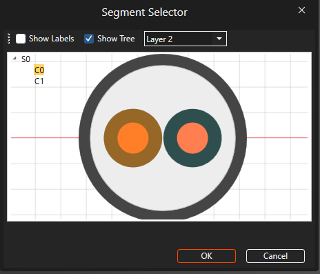
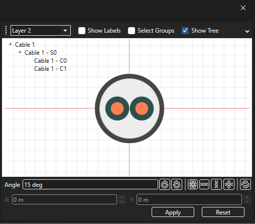
 tool. A new window will appear with the cable cross section. Select the cable on which to configure the terminations (S indicates a shield, C indicates a conductor, and each is numbered to differentiate them). Move between cable layers by using the Layers drop-down list to the top left of the cross section.
Using the Select Point
 tool, select the unterminated endpoints. They will turn into yellow dots.
After selecting the termination points, their properties can be changed within the Properties Panel. Select a property to see its definition. A list of cable properties and their definitions is provided at the bottom of this page. If cable twisting is desired, please see the next section of this page.
When editing the termination points, click on Termination [#] in the Properties Panel and look for the large pink dot on the model geometry to know which termination point is being edited.
Repeat the previous three steps to configure the end points for all of the nested cables. The cable name that is being configured will show up in the top left of the model window above the tools.

Click OK
 to create the cable. Cable will appear in the Simulation Tree nested within the Harness node.
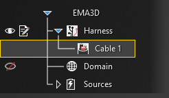
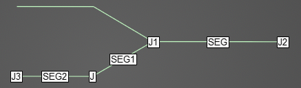
Additionally, the line in the model window will revert to its original color and it will have SEG and J labels on it indicating segments and junctions. Uncheck Harness in the Simulation Tree to hide these labels if desired.
To view a cross section of the cable after it has been created, select the
 Inspect Cross Section tool from the Harness section within the MHARNESS tab of the ribbon and then hover over the cable line. Alternatively, right click the line in the model window and select Inspect Cross Section from the pop-up menu to immediately enter the cross section editor. See the Inspect Cross Section page for more.
The placement and spacing of the cable(s) can be adjusted in the cross section editor by dragging and moving the cable(s) in the cross section or by using the tools located beneath the cross section. If the cable has multiple layers, use the dropdown menu in the top left of the Properties Panel to move between layers. Other parameters can be found by clicking the small drop-down arrow in the top right of the Properties Panel window. Note that Default Scale changes only the view scale (1 shows the cross section at full scale, 2 is half scale, etc.). Be sure to click "Apply" before closing the window to save any changes.
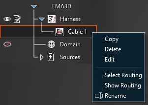
To delete, rename, copy, or edit the cable after it has been created, right click Cable in the Simulation Tree. Select Routing highlights and activates the line(s) in the model geometry to which the cable is assigned. Show Routing hides all geometry except for the line(s) in the model geometry to which the cable is assigned.
Note that when editing a cable, any changes to the cable properties are applied immediately regardless of whether the OK
button is pressed. Changes made to the cable route, however, do not apply until OK is pressed; MHARNESS will show a warning if users try to exit without clicking OK .
This behavior is useful in conjunction with turning off Automatic Harness Packing in the MHARNESS settings because automatically repacking the harness each time a route change or cable property is changed can be time consuming for the MHARNESS software.
Entry | Meaning |
|---|---|
Metadata | |
Short Name | The display name of the cable in the local tab |
|
|
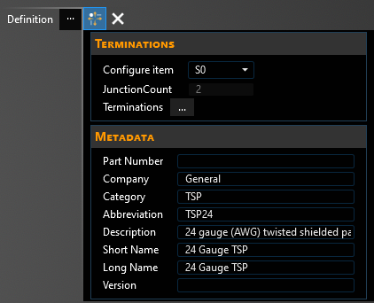
Junctions | The number of junctions in the cable route |
|
|
Configure Item | The cable on which the terminations will be edited (S stands for shield, C stands for conductor, and each is also given a number) |
|
|
Terminations | |
Method | See page on Terminations |
Configuration | See page on Boundary Conditions |
Resistance [Ω] | Termination resistance (if applicable) |
Capacitance [F] | Termination capacitance (if applicable) |
Inductance [H] | Termination inductance (if applicable) |
Conductance [S] | Termination conductance (if applicable) |
Resistance Series [Ω] | Termination series resistance (if applicable) |
Resistance Parallel [Ω] | Termination parallel resistance (if applicable) |
EMA3D - © 2026 EMA, Inc. Unauthorized use, distribution, or duplication is prohibited.