Antenna Far Field |
The Antenna Far Field probe is used to capture and visualize far field values in the form of radialE (r*E). This tool can be used to visualize antenna patterns in common formats such as RHCP/LHCP, Theta/Phi, and X/Y/Z. If additional post-processing is desired, all the antenna data is output in a human-readable format within the EMA results folder, antennaFarField_completeResults.dat.
Algorithm runtime is directly impacted by the size of the probe boundary, the angular resolution, and the domain settings of the EMA3D model. Follow the existing EMA3D workflow for making the antenna geometry, signal, and excitation. At this time, antenna simulations can use Current, Voltage, Field, or Antenna sources to drive the antenna. Any source used should a be Gaussian or Derivate of Gaussian signal types as the excitation.
Follow the existing EMA3D workflow for making the antenna geometry, signal, and excitation. At this time, antenna simulations can use Current, Voltage, Field, or Antenna sources to drive the antenna. Any source used should a be Gaussian or Derivate of Gaussian signal types as the excitation.
For additional help on the sources, refer to:
.
For additional help on the excitations, refer to:
.
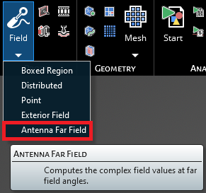
Click Field
 within the Probes section under the EMA3D tab in the ribbon. Then click Antenna Far Field in the drop-down list.
The Antenna Far Field tool will appear within the main window to define the Huygen's boundary and angular resolution for far field information. A Huygen's boundary needs to be defined surrounding the antenna structure. The Huygen's boundary can be defined using the box dragger tool or by entering the minimum and maximum extents in the entry boxes. EMA3D will automatically ensure the antenna probe aligns with the EMA3D lattice. NOTE: This boundary should be placed at least one-tenth of a wavelength away from any part of the antenna geometry.
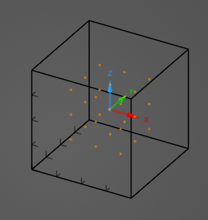
After configuring the antenna probe settings, click OK
 . The probes points on the Huygen's boundary will appear in the main window.
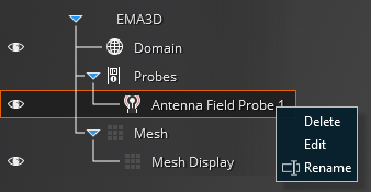
The probe can be renamed, deleted, or modified at any time by right clicking it in the Simulation Tree. The probe can also be edited by double clicking its name in the Simulation Tree.
To visualize the Antenna Far Field results, see here.
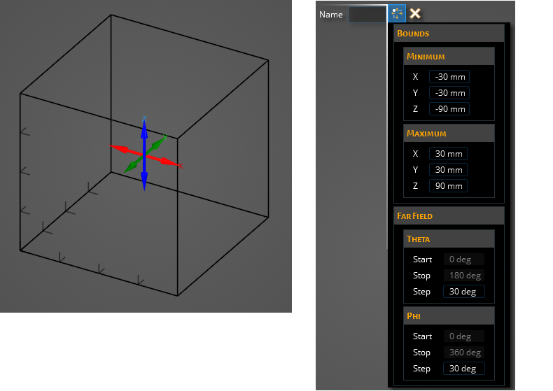
Entry | Meaning |
|---|---|
Name | Name of the probe. |
Entry | Meaning |
|---|---|
Min - X | Minimum x location of the probe. |
Min - Y | Minimum y location of the probe. |
Min - Z | Minimum z location of the probe. |
Max - X | Maximum x location of the probe. |
Max - Y | Maximum y location of the probe. |
Max - Z | Maximum z location of the probe. |
Entry | Meaning |
|---|---|
Result Domain | Antenna algorithm used during EMA3D solve. |
Result Dimension | Flag to calculate either 2D cuts or 3D sphere. |
Theta - Start | Starting angle for theta. |
Theta - Stop | Stopping angle for theta. |
Theta - Step | Angular step for theta. MUST divide within start-stop range. |
Phi - Start | Starting angle for phi. |
Phi - Stop | Stopping angle for phi. |
Phi - Step | Angular step for phi. MUST divide within start-stop range. |
Frequency - Start | Start frequency for antenna results output. |
Frequency - Stop | End frequency for antenna results output. |
Frequency - Step | Step frequency for antenna results output. |
Other Resources
EMA3D – © 2026 EMA, Inc. Unauthorized use, distribution, or duplication is prohibited.