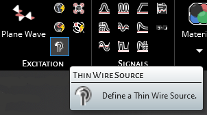
Thin Wire Source |
The EMA3D Thin Wire source tool allows users to create a thin wire to serve as an excitation source.
Click Thin Wire Source
 within the Excitations section under the EMA3D tab in the ribbon.
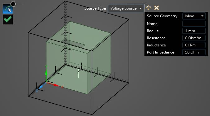
In the Properties Panel, adjust the Thin Wire source properties as desired. Hovering over the name of a property will provide an explanation of its meaning in the Properties Panel. A list of adjustable properties and their meanings is provided in the table at the bottom of this page.
In the top left of the model window, the select line
 tool has appeared and in the top right the Properties Panel has appeared.
Using the select line
tool, select the line to which to assign the thin wire source definition. It will be immediately recolored blue.
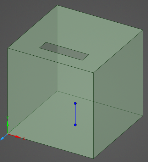
Drag the cursor to use the select point
 tool to select the point to which to assign the thin wire source location. It will be immediately recolored yellow. If you selected a Pin Injection Voltage source, the excitation point will automatically jump to the closest end point of the thin wire to where the user clicked.
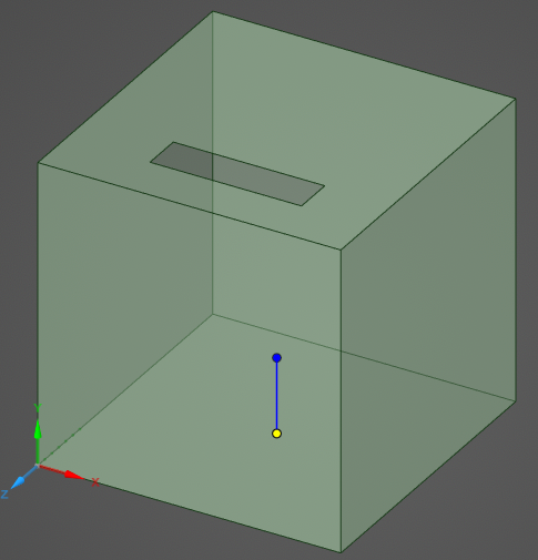
Click OK
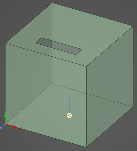
 to complete the Thin Wire source definition. The excitation point will change to a yellow dot encircled by two yellow rings.
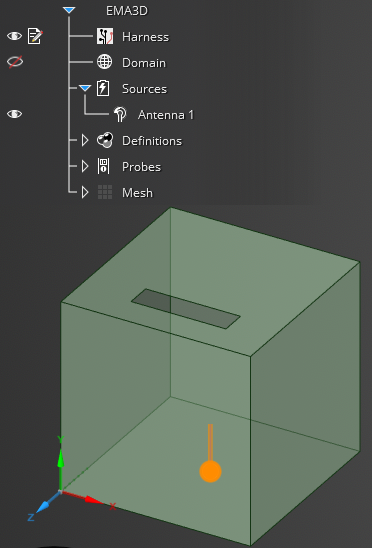
The new Thin Wire source should now appear in the Simulation Tree under Antenna # within the Sources node. Selecting Antenna # within the Simulation Tree will highlight the Thin Wire source in the model window.
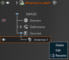
Adjust the definitions of the Thin Wire source at any time by right clicking it within the Simulation Tree and selecting Edit from the pop-up menu.
Entry | Meaning |
|---|---|
Properties | |
Source Geometry (Voltage Sources Only) | Inline - Voltage source is applied within the thin wire geometry Pin Injection - Voltage source is applied at one end of the thin wire |
In Series (Voltage Source Pin Injection Only) | True (Blue lettering) - Place the voltage source pin injection in series with the termination boundary condition False (White lettering; default) - Overwrite the termination boundary condition at the pin injection location |
Name | The thin wire source display name |
Radius [mm] | The thin wire radius |
Resistance [Ω/m] | The thin wire resistance per meter |
Inductance [H/m] | The thin wire inductance (the inherent inductance of the thin wire is calculated automatically within the solver, however, if additional inductance is desired, then it may be specified through this parameter) |
Port Impedance [Ω] | The thin wire port impedance. Default is standard 50Ω |
EMA3D - © 2025 EMA, Inc. Unauthorized use, distribution, or duplication is prohibited.