Point |
The Point field probe is a powerful tool with inherent algorithms to process data and record the data in a useful and common format. The Point field probe is similar to the "Boxed Region" field probe, but it encompasses and processes data from a single point, rather than several points.
For calculating the electromagnetic fields and the transfer functions, EMA3D performs a 5% running bandwidth average on the field data. Then, EMA3D performs a Fast Fourier Transform of each location and averages the raw values together. Finally, EMA3D then performs another pass and "smooths" them out by averaging neighboring frequencies together with a sliding window.
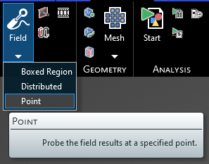
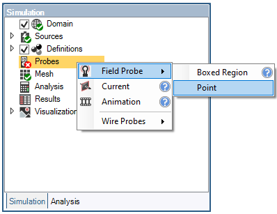
Click Field Probe
 within the Probes section under the EMA3D tab in the ribbon. Click Point in the drop-down list.
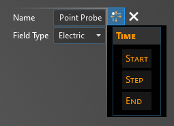
The default probe field type is Electric, suitable to measure the electric field in the assigned point. In order to measure the magnetic field, change the probe field type to Magnetic in the Properties panel. In the Properties panel, the time properties can also be adjusted.
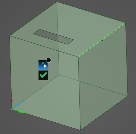
Select the point to probe in the model window—only points that match up with a defined point in the model geometry can be selected (e.g., a corner, a line midpoint, or a user-drawn point). Selectable points will be highlighted when hovered over.
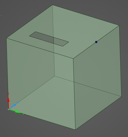
Once selected, the point probe will appear in the model window as a blue dot.
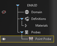
The probe should now be visible in the model window and should be added to the Simulation Tree under the Probes node.
The probe can be renamed or deleted at any time by right clicking it in the Simulation Tree. Additionally, the probe can be edited by double clicking its name in the Simulation Tree.
To visualize the Point Probe results, see here.
Entry | Meaning |
|---|---|
Name | Name of the probe. |
Field Type | Field quantity to measure. |
Entry | Meaning |
|---|---|
Start: Match Domain | Match the start time to the FDTD domain. |
Start: Value | The probe start time. |
Step: Match Domain | To which domain to match the probe time step:
|
Step: Value | The probe time step. |
End: Match Domain | Match the end time to the FDTD domain. |
End: Value | The probe end time. |
Other Resources
EMA3D – © 2026 EMA, Inc. Unauthorized use, distribution, or duplication is prohibited.