Animation |
The Animation Probe tool is used to visualize the time domain evolution of electric or magnetic fields evaluated on a specific surface(s) of the model. The animation is visualized directly in the EMA3D GUI.
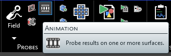
Click
 Animation within the Probes section under the EMA3D tab in the ribbon.
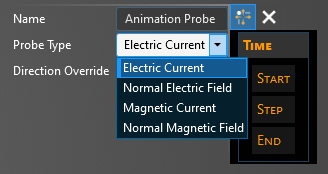
In the Properties Panel, adjust the probe properties as desired.
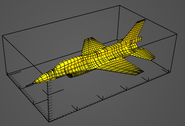
Using the select surface
 tool, select the surface(s) to probe. The surface(s) can be selected in the model window or within the structure tree. The selected surface(s) will turn yellow.
Click OK
 to complete the probe definition.
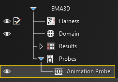
Adjust the definitions of the probe at any time by right clicking it within the Simulation Tree and selecting Edit from the pop-up menu.
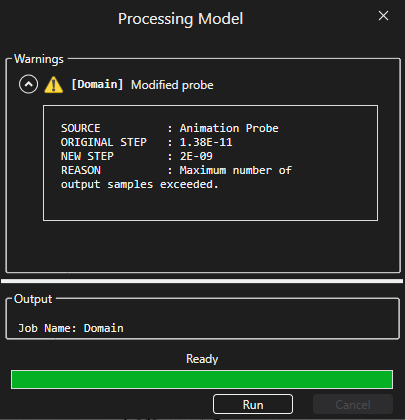
Note that there is a maximum output of 500 frames for the Animation probe. Therefore, once the user starts the model pre-processing using the Start
 button, a warning may appear reading Maximum Number of Output Samples Exceeded. EMA3D will adjust the Animation probe time step to ensure that the 500 frame threshold is met. Alternatively, close out of the warning and manually change the Step or Skip value in the probe properties panel. Then restart the simulation.
To visualize the Animation Probe results, see here.
Entry | Meaning |
|---|---|
Name | Name of the probe. |
Probe Type | The field to measure. It can be set to Electric Current, Normal Electric field, Magnetic Current, Normal Magnetic field, air conductivity, spatial charge, or absorption rate |
Direction Override | Override probed direction. |
Entry | Meaning |
|---|---|
Start - Match Domain | Match the start time to the FDTD domain. |
Start - Value | The probe start time. |
Step - Match Domain | To which domain to match the probe time step:
|
Step - Value | The probe time step. |
End - Match Domain | Match the end time to the FDTD domain. |
End - Value | The probe end time. |
Other Resources
EMA3D – © 2026 EMA, Inc. Unauthorized use, distribution, or duplication is prohibited.