Voltage |
The EMA3D Voltage difference probe measures the voltage between two specified points.
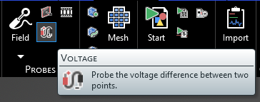
Click
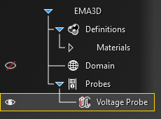
 Voltage Probe within the Probes section under the EMA3D tab in the ribbon.
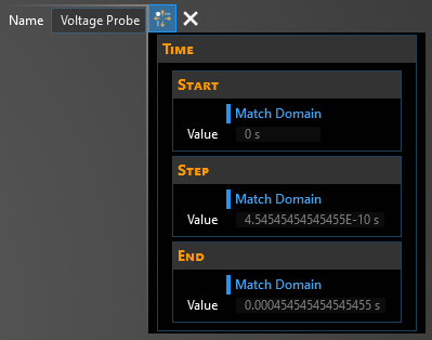
In the Properties Panel, adjust the probe properties as desired.
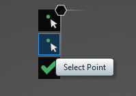
Using the select point
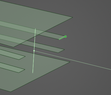
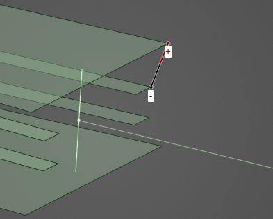
 select the negative point of the probe - only points that match up with a defined point in the model geometry can be selected (e.g., a corner, a line midpoint, or a user-drawn point). Selecting points from the Structure Tree is not supported.
Using the select point
select the positive point.
The probe will now appear as a red and black line connecting the two points in the model window.
Adjust the definitions of the probe at any time by right clicking it within the Simulation Tree and selecting Edit from the pop-up menu.
To visualize the Voltage Probe results, see here.
Entry | Meaning |
|---|---|
Name | Name of the probe. |
Entry | Meaning |
|---|---|
Start - Match Domain | Match the start time to the FDTD domain. |
Start - Value | The probe start time. |
Step - Match Domain | To which domain to match the probe time step:
|
Step - Value | The probe time step. |
End - Match Domain | Match the end time to the FDTD domain. |
End - Value | The probe.com end time. |
Other Resources
EMA3D – © 2026 EMA, Inc. Unauthorized use, distribution, or duplication is prohibited.