Exterior Field |
The Exterior Field Probe utility is used to obtain electric or magnetic field data at a point outside of the computational domain. These point locations may be at great distances from the confines of the problem space. The locations of exterior fields are specified by identifying the coordinates of the far field locations in the user interface. While most useful for probing fields outside of the domain, this probe does allow for probe locations within the domain.
The exterior field algorithm computes the total field, including the near field, the inductive field, and the far field. The Exterior Field Probe algorithm operates by computing electric and magnetic surface current densities on a far field integration surface that is just inside the domain boundary. These current densities are synthesized, with the proper retardation times, to provide the electric or magnetic fields at close or at distance points from the integration surface.
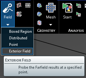
Click Field
 within the Probes section under the EMA3D tab in the ribbon. Then click Exterior Field in the drop-down list.
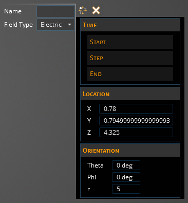
The default probe field type is Electric. To measure the magnetic field, change the probe field type to Magnetic in the Properties panel. The time, location, and orientation properties can also be adjusted.
Adjust the orientation and location in the Properties Panel to set the probe’s position and direction.
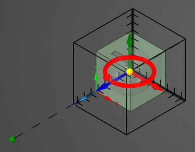
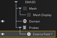
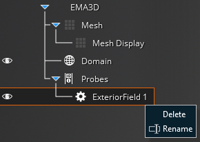
The probe will appear in the model window as a large green dot and will be added to the Simulation Tree under the Probes node.
The probe can be renamed or deleted at any time by right clicking it in the Simulation Tree. It can also be edited by double clicking its name.
To visualize the Exterior Field Probe results, see here.
Entry | Meaning |
|---|---|
Name | Name of the probe. |
Field Type | Field quantity to measure. |
Entry | Meaning |
|---|---|
Start: Match Domain | Match the start time to the FDTD domain. Blue indicates True. |
Start: Value | The probe start time. |
Step: Match Domain | To which domain to match the probe time step:
|
Step: Value | The probe time step [s]. |
End: Match Domain | Match the end time to the FDTD domain. Blue indicates True. |
End: Value | The probe end time [s]. |
Entry | Meaning |
|---|---|
X | X location of the probe. |
Y | Y location of the probe. |
Z | Z location of the probe. |
Entry | Meaning |
|---|---|
Theta | The theta coordinate of the probe. |
Phi | The phi coordinate of the probe. |
r (m) | The distance from the domain center [m]. |
Other Resources
EMA3D – © 2026 EMA, Inc. Unauthorized use, distribution, or duplication is prohibited.