Variable Grid |
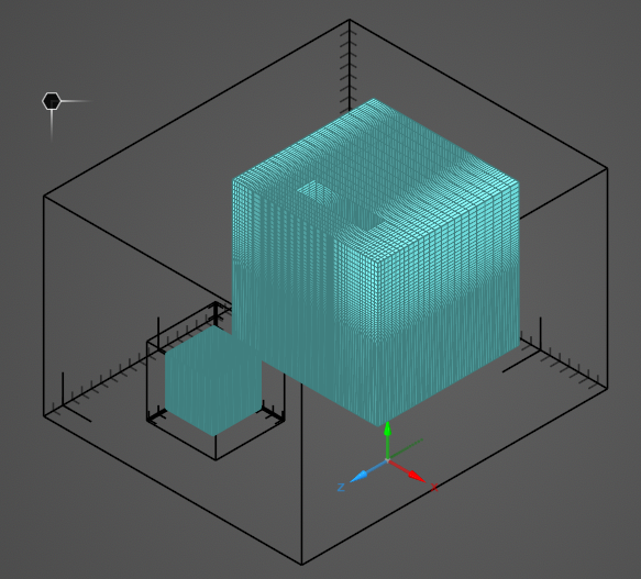
In certain cases, finer resolution may be desired in only part of the parent simulation domain. In that case, a second, smaller, nested domain can be created within the parent domain to mesh at finer resolution. A variable grid differs from a subgrid in that only one simulation is performed and the lattice spacing within the parent domain expands in size outward from the finer resolution variable grid location rather than having a hard jump in spacing as with a subgrid. See here for more technical information.
At this time, variable grids are incompatible with MHARNESS cables.
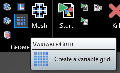
Click
 Variable Grid under the EMA3D ribbon within the Simulation section.
It is then possible to adjust the variable grid properties in the Properties Panel. The properties are outlined in the table below.
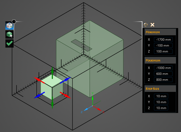
Use any of the Select Geometry tool, the drag arrows that appear onscreen, or the Maximum and Minimum Bounds in the Properties Panel to set the region for the variable grid. The variable grid must exist entirely within the parent domain.
Click OK
 to create the variable grid.
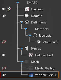
To edit the variable grid at any point, right click Variable Grid # in the Simulation Tree.
Entry | Meaning |
|---|---|
Minimum [mm] | The minimum spatial bounds (X, Y, Z) of lattice coordinates for the variable grid |
Maximum [mm] | The maximum spatial bounds (X, Y, Z) of lattice coordinates for the variable grid |
Step Size [mm] | The mesh cell dimensions along the three Cartesian axes (X, Y, Z) for the variable grid. |
EMA3D - © 2025 EMA, Inc. Unauthorized use, distribution, or duplication is prohibited.