Surface |
The lattice surface tool can be used to create a plane that extends across the entire domain lattice. This tool is especially useful for creating animation probes of geometry cross sections.
After the domain is defined, click the
 Lattice Surface tool within the Geometry section under the EMA3D tab in the ribbon.
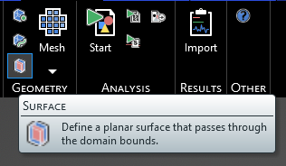
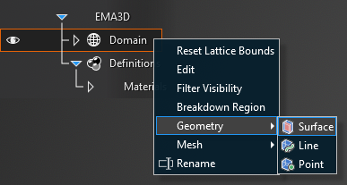
Alternatively, right click Domain in the Simulation Tree, then select Geometry in the pop-up menu, and finally select
Surface.
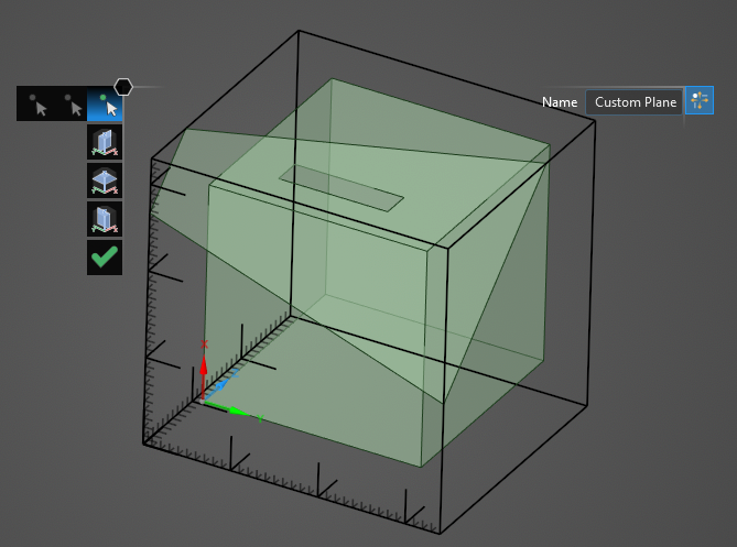
Four options for creating the plane appear within the model window:
Custom Plane
The default option is to create a custom plane by choosing three points that lie within the plane. To set the plane, select
 if it is not selected. Hover over the lattice boundary on which the point will be made. The lattice mesh will appear. Move the cursor over the mesh - the point coordinates will appear. Select a point on the lattice boundary within the desired plane and repeat two more times. A greyscale representation of the plane will appear as the points are selected. The final plane will appear once the third point is selected. This option can be used to create the most custom plane.
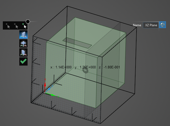
Create X-Z Plane
This option creates an X-Z plane that stretches across the entire boundary at a selected Y value. To set the plane, select
 . Hover over the domain, the lattice mesh will appear. Move the cursor over the mesh - the point coordinates will appear, as will a greyscale representation of the plane. Moving along the Y axis, select a point on the lattice boundary for the plane. The final plane will appear.
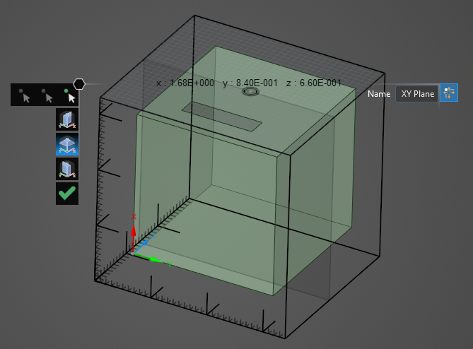
Create X-Y Plane
This option creates an X-Y plane that stretches across the entire boundary at a selected Z value. To set the plane, select
 . Hover over the domain, the lattice mesh will appear. Move the cursor over the mesh - the point coordinates will appear, as will a greyscale representation of the plane. Moving along the Z axis, select a point on the lattice boundary for the plane. The final plane will appear.
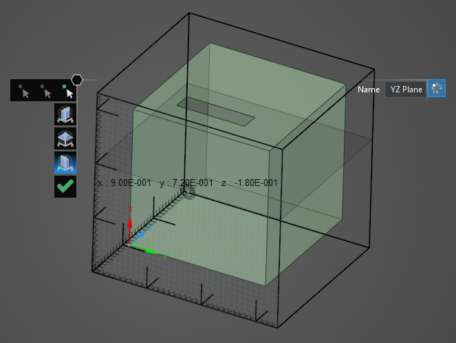
Create Y-Z Plane
This option creates an Y-Z plane that stretches across the entire boundary at a selected X value. To set the plane, select
 . Hover over the domain, the lattice mesh will appear. Move the cursor over the mesh - the point coordinates will appear, as will a greyscale representation of the plane. Moving along the X axis, select a point on the lattice boundary for the plane. The final plane will appear.
Click OK
 to close the lattice surface tool.
Entry | Meaning |
|---|---|
Name | Plane name |
EMA3D – © 2026 EMA, Inc. Unauthorized use, distribution, or duplication is prohibited.