Point |
The lattice point tool can be used to create a point that lies exactly on the domain lattice boundary mesh, which ensures that the point will still be meshed (assuming it has a material assigned to it). The lattice point tool can also be used to create a point that lies exactly on the subgrid domain lattice boundary mesh - the only difference is in how the tool is opened, as outlined below.
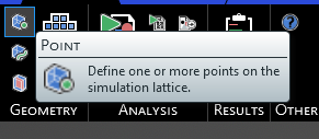
Click the Point tool
 under EMA3D in the Ribbon within the Geometry section.
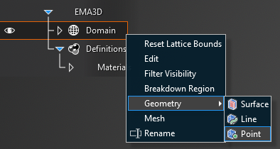
Alternatively, right click Domain in the Simulation Tree, then select
Geometry in the pop-up menu, and finally select Point.
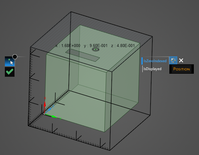
Hover over the lattice boundary on which the point will be made. The lattice mesh will appear. Move the cursor over the mesh - the point coordinates will appear.
Click on a mesh location to set the point.
Alternatively, after selecting the point tool, the point can be placed using the properties panel.
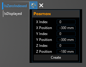
Select Zero Indexed to use (0,0,0) as the start index, if desired. Select Display Point to display the point coordinates, if desired.
The X, Y, and Z points can be set using either the mesh cell number (an integer indicating how far from the center point the mesh cell is) or using the mm coordinate itself (only coordinates that lie exactly on the mesh can be used or EMA3D will round to the nearest mesh location).
Entry | Meaning |
|---|---|
IsZeroIndexed | Start indexing at (0,0,0) rather than (1,1,1) |
IsDisplayed | Display coordinates of starting index |
Entry | Meaning |
|---|---|
X Index | X index of point |
X Position | X coordinate of point |
Y Index | Y index of point |
Y Position | Y coordinate of point |
Z Index | Z index of point |
Z Position | Z coordinate of point |
Create | Creates the point at the selected mesh location |
EMA3D – © 2026 EMA, Inc. Unauthorized use, distribution, or duplication is prohibited.