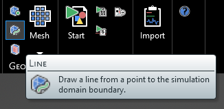
Line |
The lattice line tool can be used to create a line that extends from a point or other geometric entity to a point exactly on the domain lattice boundary mesh, which ensures that the line will be meshed to the boundary (assuming the line has a material or source assigned to it). This tool is especially useful when creating a current source injection line, which must be attached to a boundary. The lattice line tool can also be used to create a line that extends from a point or other geometric entity to a point exactly on the subgrid domain lattice boundary mesh - the only difference is in how the tool is opened, as outlined below.
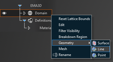
After the domain is defined, click the
 Lattice Line tool within the Geometry section under the EMA3D tab in the ribbon. For the subgrid domain, right click Sub-grid in the Simulation Tree, select Geometry from the pop-up menu, and then select Line.
Alternatively, right click Domain in the Simulation Tree, then select
Geometry in the pop-up menu, and finally select Line.
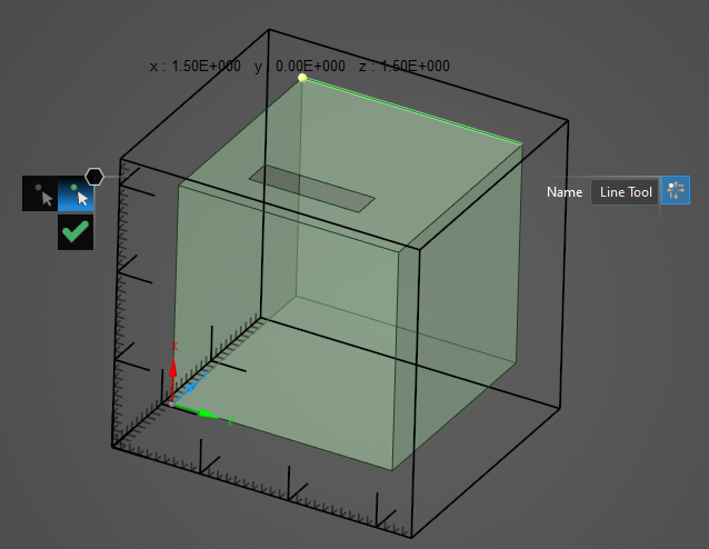
Select the point on the model within the domain where the line will begin. The coordinates will appearwhen hovering over a point and the point will be highlighted yellow.
Hover over the lattice boundary on which the point will be made. The lattice mesh will appear. Move the cursor over the mesh - the point coordinates will appear.
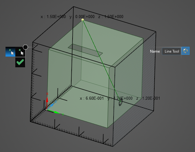
Click on a mesh location to set the end point of the line.
Click OK
 to close the lattice line tool.
Entry | Meaning |
|---|---|
Name | Line name. |
EMA3D – © 2026 EMA, Inc. Unauthorized use, distribution, or duplication is prohibited.