Domain |
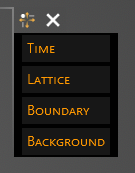
The first step in setting-up an EMA3D simulation is the definition of the solution domain. Four parts comprise the domain:
Time (the time interval, frequency range, and increment method over which to run the simulation)
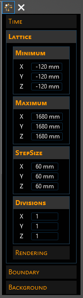
Lattice (the dimensions of the solution volume, the mesh cell size, and the number of processors for each Cartesian direction)
Boundary (the boundary conditions to be applied to the faces of the solution volume)
Background (the electromagnetic properties of the material with which the solution volume is filled). Rendering allows adjustments to the settings for the visualization of the solution domain.
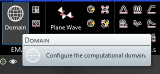
Click
 Domain within the Domain section under the EMA3D tab in the ribbon.
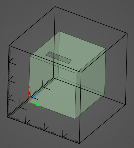
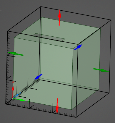
The lattice will immediately appear in the model window. By default it encapsulates the model geometry.
Adjust the domain properties in the Properties Panel.
Click OK
 to complete the domain setup.
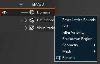
To edit the domain at any point, right click Domain in the Simulation Tree. Reset Lattice Bounds resets the dimensions of the solution volume to the smallest box that fully encapsulates the model geometry. Edit brings up the Properties Panel. Geometry and Mesh are discussed here. Be sure to have EMA3D selected in the Stage Navigator, otherwise the Simulation Tree will not be visable.
Time Summary
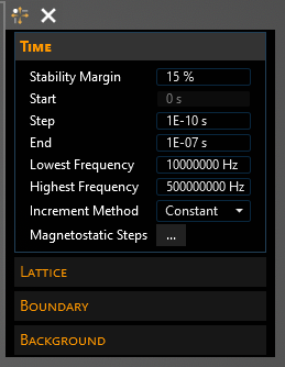
The Time properties allow for adjusting the time range and time step, the frequency range of interest, and the increment method for the EMA3D simulation.
Magnetostatic
For magnetostatic or quasi-magnetostatic configurations, the displacement current becomes small or negligible allowing the permittivity values of associated materials to be increased without significantly impacting model electromagnetic behavior. Increasing the permittivity values enables an increase in the value of the time step. An increased time increment value can significantly reduce the number of time steps required to complete a temporal description. Magnetostatic time steps are often employed for lightning analysis investigations.
Specification of magnetostatic time steps still requires the specification of constant time steps. The constant time step specification defines the initial time step and the computational time window. The magnetostatic time steps are specified in addition to the constant time step information. The magnetostatic time steps information specifies the manner in which the permittivity is to increase.
Defining Magnetostatic Time Steps
If it is not open, navigate to the domain Properties Panel by right clicking Domain within the Simulation Tree and selecting Edit from the pop-up menu.
Under the Time properties of the domain Properties Panel, select the box next to the Increment Method and change it to Magnetostatic. The default increment method is constant time stepping.
Entry | Meaning |
|---|---|
Stability Margin | Minimum Stability margin for Courant Criterion
|
Start | Start Time [s] |
Step | Step Time [s] |
End | End Time [s] |
Lowest Frequency | Lowest frequency of interest |
Highest Frequency | Highest frequency of interest |
Increment Method | Constant or Magnetostatic time stepping |
Magnetostatic Steps | The magnetostatic time steps and permittivity increase factors. Only applies if Magnetostatic is the selected increment method |
Import Magnetostatic Steps | Choose to import a setup for magnetostatic time stepping |
Lattice Options Summary
EMA3D is based on an FDTD method suitable to solve Maxwell's equations in a finite solution volume. In EMA3D, the solution volume is denoted as Lattice.
The Lattice is a parallelepiped on whose faces the boundary conditions are applied. The dimensions of the lattice, along with the three Cartesian directions, are affected by the boundary conditions. The proper distance to place the boundaries from the object being modeled depends upon the finite difference boundary condition used.
The domain lattice settings can be set within the domain Properties Panel under Lattice.
Lattice Options Instructions
To access the Lattice properties, right click Domain in the Simulation Tree and select Edit.
The geometrical dimensions of the simulation lattice can be assigned by editing the Minimum and Maximum sections in the Properties Panel or by dragging the six directional handles in the model window. By default, the domain lattice encapsulates the model geometry when
Domain is first selected.
Entry | Meaning |
|---|---|
X | Minimum X spatial boundary location. |
Y | Minimum Y spatial boundary location. |
Z | Minimum Z spatial boundary location. |
X | Maximum X spatial boundary location. |
Y | Maximum Y spatial boundary location. |
Z | Maximum Z spatial boundary location. |
Preserve Mesh | If true, preserves mesh spacing. |
X | X direction lattice size |
Y | Y direction lattice size |
Z | Z direction lattice size |
X | # of X spatial divisions for parallel processing |
Y | # of Y spatial divisions for parallel processing |
Z | # of Z spatial divisions for parallel processing |
Color | Color to use when rendering domain |
Shade | Shade the sides of the domain |
Major Gridlines | Display major gridlines |
Minor Gridlines | Display minor gridlines |
Cell Numbers | Display cell indices |
Boundary Options Summary
The domain boundary settings can be set within the domain Properties Panel under Boundary.
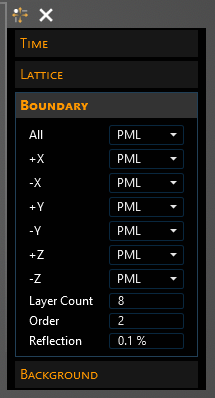
The boundary condition can be individually assigned for each face of the simulation domain or the same boundary condition can be assigned to all faces of the simulation domain using the All entry. However, a PML boundary condition must be speicified on ALL boundary faces.
Entry | Meaning |
|---|---|
All | Boundary conditions (BC) on all sides |
+X | BC on upper YZ Plane |
-X | BC on lower YZ Plane |
+Y | BC on upper XZ Plane |
-Y | BC on lower XZ Plane |
+Z | BC on upper XY Plane |
-Z | BC on lower XY Plane |
Layer Count | The number of perfectly matched layers to be applied to the solution domain face |
Order | The order of the conductivity function. It specifies how the conductivity increases from the front to the back layer |
Reflection | The amount of electromagnetic energy reflected back into the numerical problem space |
Background Options Summary
The domain solution volume material properties can be set within the domain Properties Panel under Background.
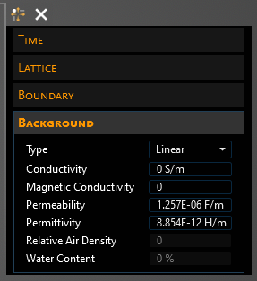
By default, a single linear background media enveloping the entire problem space and possessing vacuum electromagnetic parameter values is used.
Entry | Meaning |
|---|---|
Type | Linear or nonlinear |
Conductivity | Background conductivity [S/m] |
Magnetic Conductivity | Background magnetic conductivity |
Permeability | Background absolute permeability [H/m] |
Permittivity | Background absolute permittivity [F/m] |
Relative Air Density | Background relative air density [0-1] |
Water Content | Background absolute percentage of water content [0-6%] |
EMA3D – © 2026 EMA, Inc. Unauthorized use, distribution, or duplication is prohibited.