Updated Materials Workflow |
EMA has had a goal of using Discovery’s native materials for a while. EMC Plus 2025R1 is the first release that integrates EMC Plus Materials with Discovery’s materials. The pairing has improved the rendering of material assignments, improved the permanence of assignments for items when moving them in the Design Tree, along some other improvements.
The marriage of the two material paradigms affects the material workflow in a few ways that are described below. The changes described below are restricted to PEC and Isotropic materials in EMC Plus. While that should cover the most common use cases, it isn’t exhaustive of all EMC Plus workflows. The material assignments accessed via the Charge ribbon are completely unaffected.
This topic contains the following sections:
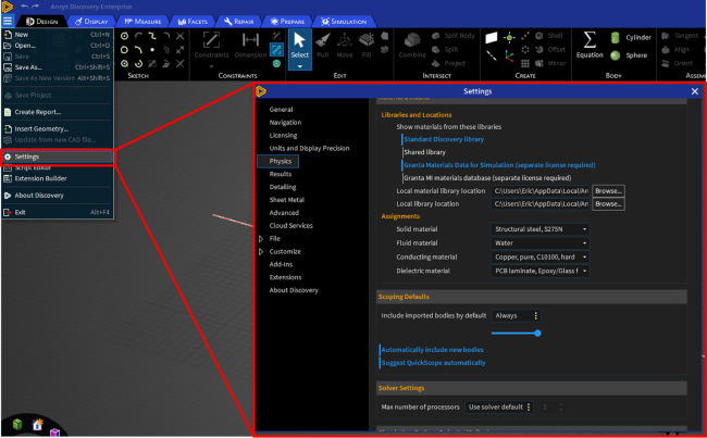
Discovery assumes that all closed volumes and closed surfaces will have a material assignment. To satisfy this, Discovery will assign any material-less geometry a default material. The assignment will be applied at any time that Discovery finds geometry without a material, not just during geometry creation or modification. If Discovery’s Physics functions are enabled (depends on licensing, configuration, and launch arguments), then the user can change their default materials using Discovery’s settings.
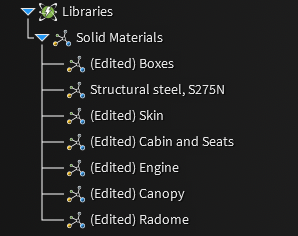
Material assignments can be inspected and modified using Discovery’s native UI’s available via the Physics Tree or the Library Tree. In its native workflows, Discovery only allows material assignments on bodies.
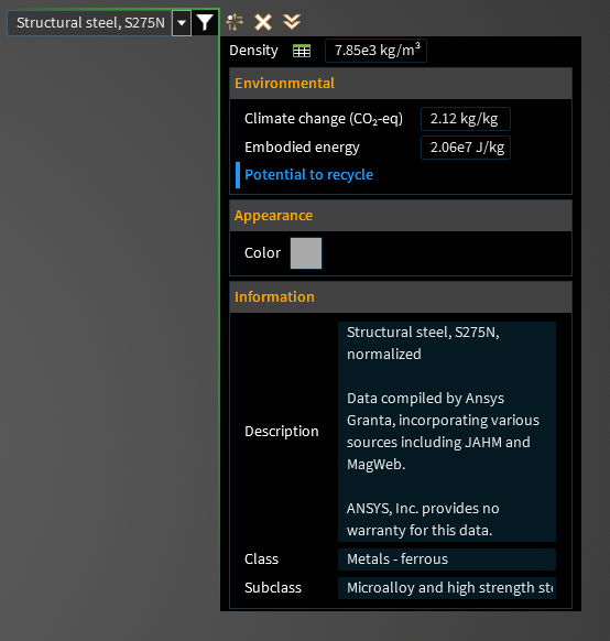
Discovery offers several libraries of materials with some simulation parameters, including several useful for electromagnetics simulations. Depending on the available licenses and the active mode of Discovery, these parameters may or may not be editable by the user. In the default configuration used by EMC Plus and Charge Plus, the default parameters are not modifiable. The built-in Discovery Edit Material UI is shown in Figure below.
EMC Plus uses materials as one of the ways to define a region’s properties during a simulation. Other definitions include sources, structures, probes, etc. Materials can be assigned to bodies, surfaces, and lines for use in EMA3D simulations.
There are several types of materials available to use in EMC Plus/EMA3D simulations. They are: PEC, PMC, Isotropic, Nonuniform Isotropic, Anisotropic, and Frequency Dependent.
Some workflows in EMC Plus use geometry without material assignments. Examples are probe placements like planes used to create cross-sectional animation probes, structures like MHarness cables, barriers, etc.
It is common that users need to enter electromagnetic properties for materials. That can be for the sake of doing parametric design studies, having measured data for their specific material, etc. Some EMA3D materials require niche, uncommon parameters for specific physics (electron yields, anisotropic properties, etc.) that are typically not available in material libraries. It’s required that those parameters are editable in the UI.
There are several workflow discrepancies to reconcile between the Discovery material workflow and the EMC Plus/EMA3D material workflow. Itemized, they are:
EMA3D materials sometimes require uncommon physical properties of materials; Discovery’s library only has a subset of the required material properties
EMA3D users require the ability to set all necessary electromagnetic properties of materials; Discovery typically doesn’t allow the user to modify electromagnetic properties
EMA3D requires that some geometry not have material assignments; Discovery requires that all solid geometry have material assignments
EMA3D requires assignments for bodies, surfaces, and lines; Discovery UI’s only allow assignments to closed bodies.
Ansys and EMA have partnered to find solutions and workflows to reconcile these differences. This chapter describes the workflow(s) available and how to use them.
Ansys extended their API so that material properties could be added to Discovery materials by EMC Plus and Charge Plus. This is done on a per-material basis and only on materials that are generated/modified by EMC Plus and Charge Plus.
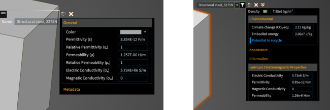
In other words, users must use the EMC Plus Tools to generate a material for the appropriate electromagnetic parameters to be initialized. Once initialized, those parameters can be modified by either the EMC Plus Tools or the Discovery UI’s. For example, the Isotropic Material Tool is identified in the figure below.

If the parameters aren’t initialized, the material will be ignored by EMC Plus and the EMA3D simulation. In that case, the edit tool accessible via right-clicking in the Library Tree will look like 2 previous pictures ago.
If the material has been initialized using one of the material tools in the EMA3D ribbon, then the parameters are available for editing in both the EMA3D material tools and in the Discovery UI’s.
The system described above allows all of the required parameters to be defined and modified. Importantly users must initialize the material via the EMA3D Material tools for the parameters to be created and modified.
For CAD models that have native Discovery materials defined in them that don’t have initialized EMA3D material properties, those material assignments won’t be used for EMA3D simulations. There are ways to initialize those parameters, which will be discussed later.
As mentioned, EMA and Discovery are each built around different assumptions for default material assignments and whether geometry without an assignment is valid. Discovery assumes that geometry must have an assignment, while EMA3D does not require it.
Both treatments may be useful depending on the use case. EMA has added a new user setting in EMC Plus and Charge Plus for the user to set how to treat Discovery material assignments that don’t have EMA3D parameters defined. The setting is available in the “Settings” button in the EMA3D tab and is labelled “Discovery Material Behavior.”
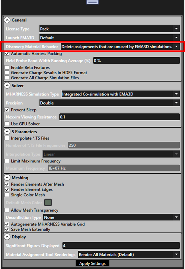
The three possible settings and their behaviors are listed below.
“Delete assignments that are unused by EMA3D simulations”
This mode constantly monitor for material assignments that are unassociated with EMA3D material parameters and deletes those material assignments in Discovery
This is the default and recommended for users familiar with previous versions of EMC Plus and Charge Plus
In this mode, material assignments in the Library Tree will only show assignments used in the EMA3D simulation.
“Convert unused assignments to EMA3D isotropic materials.”
This mode constantly monitors for material assignments that are unassociated with EMA3D material parameters and initializes the missing parameters based on information in the material library.>
Material assignments in the Library Tree will have entries created for them in the EMA3D Simulation Tree under Definitions then Materials then Isotropic
In this mode, it is impossible to create geometry without a material assignment defined for EMA3D simulations.
Even geometry created before switching to this mode will get the default Discovery material treatment as Discovery constantly monitors for geometry without assignments and creates assignments for them.
This mode may be useful for converting existing structural CAD with materials defined for structural analyses into simulation models for EMA3D.
It is not recommended for typical EMA3D workflows that require building geometry for sources, probes, etc.
“Ignore the unused assignments (legacy behavior).”
This mode constantly monitors for material assignments that are unassociated with EMA3D material parameters and labels them as ignored in the Library Tree. The label is “[Ignored by EMC Plus]”
This mode will remove the ignore label if the material assignment has the EMA3D simulation parameters are initialized by a user action.
This mode lets the user primarily use the EMA3D Simulation Tree instead of the Library Tree, like in previous releases.
In this mode, renderings for EMA3D materials will still be accessed via clicking in the Library Tree (different than in previous releases).
This mode is recommended as a debugging step or to improve performance on large models.
EMA3D simulations require assignments on bodies, surfaces, and lines. Discovery’s workflows only require them on bodies. Ansys expanded their API’s to allow assignments on surfaces and lines. However, Ansys didn’t want to clutter their existing workflows for users by exposing that capability in their material tools. Discovery’s material UI’s allow users to make assignments to bodies, but not to surfaces and lines.
EMC Plus and Charge Plus material tools allow making assignments on bodies, surfaces, and lines (where appropriate). To make assignments to surfaces and lines, users must do so via EMC Plus and Charge Plus tools.
The renderings for the assignments will show up when clicking in the Library Tree for bodies, surfaces, and lines. No special care is needed when inspecting the different types of assignments.
It is possible for EMA3D simulations for a body to have one material definition, a surface on that body to have a different assignment, and for a line of that surface to have another different assignment. That is still possible with the new tool configuration.
As a reminder, all the changes for 25R1 are restricted to PEC and Isotropic Materials. Other material types for EMC Plus and Charge Plus simulations are unaffected.
To Create a New Isotropic Material
To create a new isotropic material, use the tool in the EMA3D ribbon shown in the figure below.
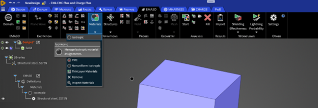
The tool will open with some default values populated in.
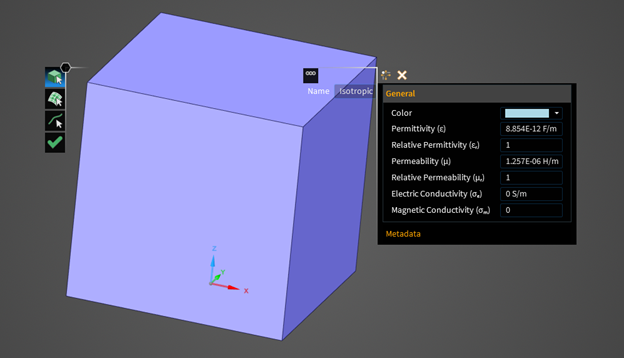
The right-hand side of the tool has all of the typed entries for the material (name, parameters, and metadata).
From here, the user can enter their desired name in the “Name” entry or in “Short name” entry in the “Metadata” region.
The user can select the material color and electromagnetic properties in the “General” region.
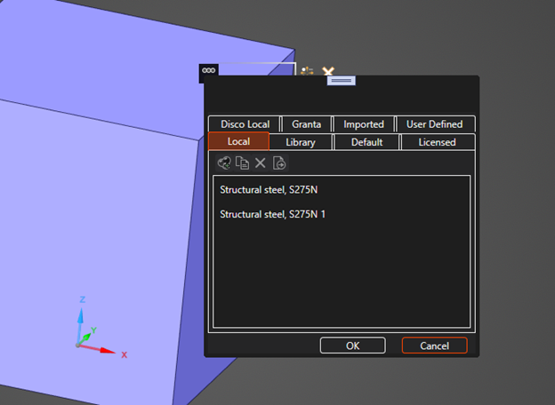
If the user wants to use a material from a library (Discovery or EMC Plus library), they can open the Material Library Selector popup by clicking the “Material Libraries" button. From there, the user will have the option to import a material from one of Discovery’s several libraries (Granta, Default, Licensed, Imported), their personal libraries (Disco Local and User Defined), or from EMC Plus’ library (Library). See figure below for the available tabs in the popup. The available parameters for the selected material will be loaded in.
The geometry selection mode is toggled on the left-hand side of the tool. The user can choose between selecting bodies, surfaces, or lines.
The left-hand side of the tool also has the green check mark which is used to complete the tool action. The green check mark must be clicked for the material to be generated and for the assignment to take effect. Any modifications made in the tool can be cancelled by hitting the escape key to leave the tool any time before the green check mark is clicked.
When the green check mark is clicked, the new material will be created and the assignments put in place. At this time, if the provided name in the tool isn’t unique, the name will have an increasing number added to the end of the name until a unique name is found. The first unique name will be used. For example, if “Isotropic” and “Isotropic 1” already exist and the user enters “Isotropic” as the name for a new material, that material will be generated as “Isotropic 2.”
Once the material is made, the material will appear in the EMA3D Simulation Tree and Library Tree with the provided name. Hovering over or clicking the material in the Library Tree will render the locations of the assignments for that material.
If you delete the Material in the EMA3D Simulation Tree, the associated entry in the Library Tree will also be removed.
If all the assignments for a material are removed, then that entry in the Library Tree will disappear. However, that material’s node in the EMA3D Simulation Tree will persist for later use. If the user wants it gone, they will have to specifically delete that material in the EMA3D Simulation Tree.
Editing an Isotropic Material’s Properties
After a material has been generated (either by using the EMA3D Material tool or via the “Convert” user setting for Discovery materials), its material parameters can be modified the following ways:
Right clicking the material assignment in the Library Tree and selecting “Edit”
Right clicking the material in the EMA3D Simulation Tree and selecting “Edit Assignments.”
Opening the appropriate EMA3D Material tool from the ribbon, open the material library popup, and selecting the existing material from the “Local” tab in that popup
Changes made to the properties are saved only when the green check mark is clicked.
Editing an Isotropic Material’s Assignments
In all cases, users can edit where a material is assigned by right clicking the material in the EMA3D Simulation Tree and selecting “Edit Assignments.” This will open the appropriate tool with the material loaded in. From there, the user can add or remove bodies, surfaces, or lines to the assignment by using the different selection modes of the tool.
Users can open the appropriate material tool from the EMA3D ribbon and select their desired existing material from the material library selector popup, as shown in the figure above. From there, that material will load into the tool and the assignments can be modified.
If a user is only making body assignments, they can opt to use the Discovery UI’s which are not documented here. Body assignments made using the Discovery UI for materials that were generated for EMC Plus will be honored in EMA3D simulations.
Please note that changes made to the assignments must be saved by clicking the green check mark.
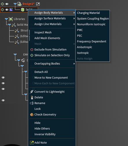
Users can also right click geometry and use the various material assignment commands available to assign isotropic materials to the selected geometry. Doing so will open the material library selector tool to select the material to use.
Using PEC (Perfect Electrical Conductor) Materials
Generally, PEC behaves the same as Isotropic materials except without parameters to define. Only one PEC material can exist at a time and can be assigned to any mixture of bodies, surfaces, and lines. The PEC material will appear in both the EMA3D Simulation Tree and in the Library Tree.
There are no parameters to modify for PEC, but assignments can be made or modified the same way as described above for isotropic materials.
EMA3D - © 2026 EMA, Inc. Unauthorized use, distribution, or duplication is prohibited.