Anisotropic |
In EMA3D, anisotropic materials are linear and frequency independent. Anisotropic materials include both electric and magnetic lossy materials characterized by user-supplied entry values in the matrices of the conductivity, the permittivity, the permeability, and the magnetic conductivity tensors. If anisotropic materials overlap, then the last one defined takes precedence.
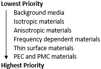
In the case of coincident or overlapping materials, materials are assigned the following priority:
Check to make sure all of the relevant structures in the Structure Tree are checked to make them visible.
Click Materials
 within the Definitions section under the EMA3D tab in the ribbon.
Click
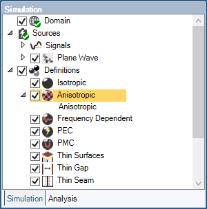
 Anisotropic in the drop-down list.
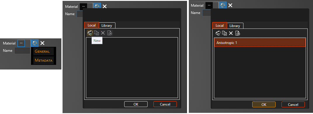
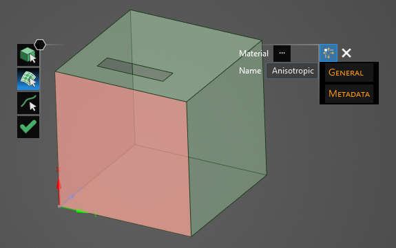
In the Properties panel select the ellipsis to the right of Material. A new window will appear. In the pop-up window, under the Local tab, select New
 .
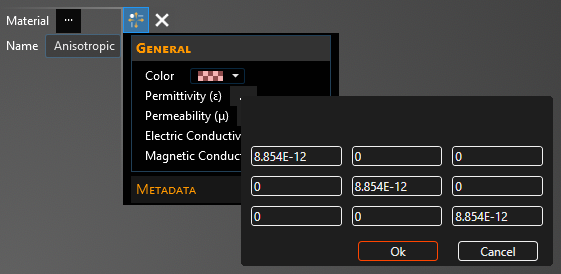
.Double click to select the first definition in the list Anisotropic. Click General to view and change any property values. Select a material property to see its definition. A list of material properties and their definitions is provided at the bottom of this page. The color is in A, R, G, B format and choosing an A between 0 (most transparent) and 255 (opaque) can make the color and mesh semi-transparent. The next section discusses how to change the anisotropic material matrix.
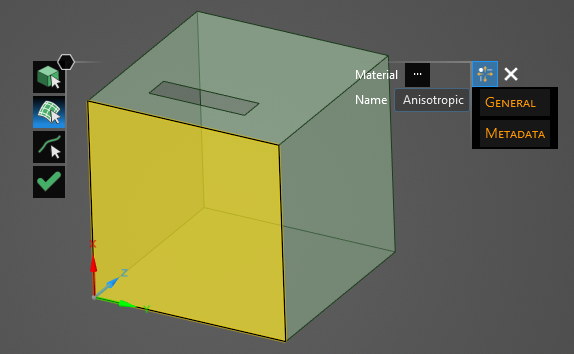
Click on the appropriate selection tool (i.e., body
 , surface
 , or line
 ) tool in the top left of the model window to restrict the assignment definition.
To assign material properties, either select the geometric entity in the model window or in the Structure Tree.
The selected surfaces will be recolored in the model window.
To hide the color and revert to the original, more transparent view, click the eye next to Anisotropic under the Definitions node in the Simulation Tree.
Repeat the above steps to assign as many materials as desired.
Click
 to complete the material assignments.

Entry | Meaning |
|---|---|
Material Libraries | Local anisotropic definition to assign to the geometry. |
Name | Name of the material. |
General Options Summary
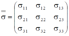
Anisotropic material parameters are based on tensor notion as denoted in the matrix below:
Entry | Meaning |
|---|---|
Color | Rendering color of the material. |
Permittivity (ε) | Material absolute permittivity. |
Permeability (μ) | Material absolute permeability. |
Electric Conductivity (σₑ) | Material electric conductivity. |
Magnetic Conductivity (σₘ) | Material magnetic conductivity. |
Entry | Meaning |
|---|---|
Part Number | Part number of material (if any). |
Company | Company of material (if any). |
Category | Category of material (if any). |
Abbreviation | Abbreviation of material (if any). |
Description | Description of material (if any). |
Short Name | Short name description of material (if any). |
Long Name | Long name description of material (if any). |
Version | Version of material (if any). |
Other Resources
EMA3D – © 2026 EMA, Inc. Unauthorized use, distribution, or duplication is prohibited.