Boundaries |
Boundary Conditions are an option for internal and coupled charging simulations. For internal charging simulations the user may set a constant voltage. Use of the Boundary Conditions for a coupled charging simulation allows the user to either have a constant potential applied, similar to that of a pure internal charging simulation, or CHARGE can use the surface potential from the surface charge solver and apply that as a boundary conditon for the internal FEM solver. If the latter is chosen the, user is allowed to have the applied boundary condition be the average of all the surface mesh cells at the surface of interest, or use the surface potential on cell by cell basis. These resulting fields can influence the simulation by either affecting the level of incoming radiation or by altering charge migration within the material.
Setting up boundary conditions is a simple process in CHARGE, with the instructions below for creating either the strictly internal charging case or if doing a coupled simulation, followed by assigning them to the surface of choice.
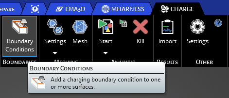
Click on the Boundary Conditions button in the Definitions section of CHARGE.
This will open up the default properties menu for an charging boundary condition shown below.
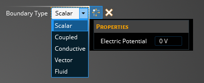
The tables below describe the different Charging Boundary Types.
Scalar Charging Boundary Type-have a constant voltage applied to a surface during the charging simulation:
ScalarProperties
Meaning
Electric Potential [V]
Define the potential value at the boundary. Leave this at 0 if you want a grounded surface or give it any value either positive or negative depending on the polarity you want
Coupled Charging Boundary Type-have the surface solver coupled to boundary condition of the internal simulation:
CoupledProperties
Meaning
Average
Applies the average of all the surface cells potentials to the entire surface of the internal charging boundary condition
Independent
Sets the coupling of the surface cells to the internal cells on a cell by cell basis
- Remaining Boundary Types
Types
Descriptions
Conductive
Set the boudary type to conductive
Vector
Electric Field Strength [V/m]
Vector Axis
Fluid
Electric Potential [V]- Define the electric potential
Fluid Temperature [K]- Define the temperature
Fluid Density [kg/m3]- Define the density
Fluid Velocity [m/s]- Define the velocity in the X, Y, and Z directions
Once you've set the coupling method, you will need to assign the boundary condition to the desried surface by following the directions below in "Assigning Boundary Condition to Surface".
Now be it either a Standard or Coupled boundary condition the user has chosen, you will need to assign it to the surfaces of the model you want the condition applied. In the top left of the model window, there is a Select Surface
 tool, and a Complete
  button.

Make sure you have the Select Surface
tool selected and using your cursor select the surface(s) of you model you want to apply the boundary conditions to. As you do so you will see the selections highlight yellow.
Once you have selected all of the surfaces you want assigned to a boundary condition, press the Complete
button to finalize the assignments.
The user will see the Boundary Condition they've created in the structure tree under Definitions and can deselect it here to toggle the color visualization of it on the model. Additional boundary conditions can be added to the tree and assigned to the model. If there are no more assignments to be made, the user can go on to the meshing portion of the simulation setup.
EMA3D - © 2025 EMA, Inc. Unauthorized use, distribution, or duplication is prohibited.