Plane Wave Drive |
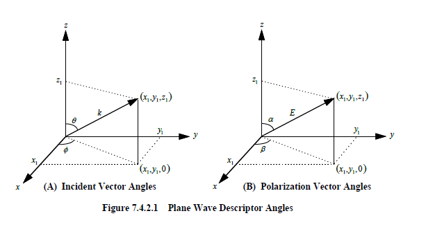
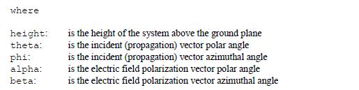
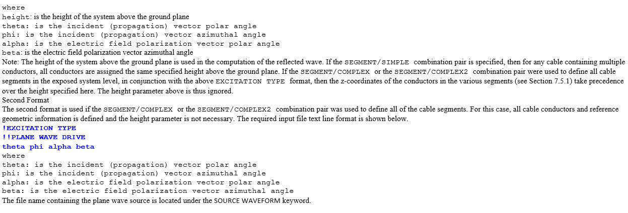
When using a plane wave source, the incident direction must be defined along with the electric field polarization direction. Two angles are used to specify the incident direction. These angles (θ,ɸ) are defined in Figure 7.4.2.1A. The variable θ is the incident direction polar angle and ɸ is the incident direction azimuthal angle. Like the incident vector, two angles are also used to specify the electric field polarization direction. These angles (α,β) are defined in Figure 7.4.2.1B. The variable α is the polarization direction polar angle and β is the polarization direction azimuthal angle. When using plane wave illumination, the source is properly time retarded at various locations on the system to produce realistic results.
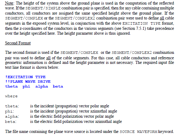
If a wire reference or ground is desired, then the SEGMENT/COMPLEX or the SEGMENT/COMPLEX2 combination pair must be used. Therefore, when the SEGMENT/SIMPLE combination pair is specified, the reference or ground is assumed to be a ground plane at the z-coordinate of, z=0.0.
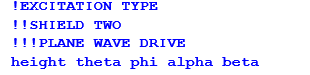
There are two input file text line formats used to specify plane wave excitation. These formats depend upon the manner in which the
MHARNESS® cable segments and conductors were defined (see Section 7.5.1). When PLANE WAVE DRIVE is specified, all segments in the exposed system level must be specified with the SEGMENT/SIMPLE (with coordinate ends specified) combination pair or all segments in the exposed system level must be specified with the SEGMENT/COMPLEX or the SEGMENT/COMPLEX2 combination pair.First Format The first input file format is necessary if the SEGMENT/SIMPLE (with coordinate ends specified), combination pair was used to define all cable segments in the exposed system level. In this case the transmission line impedance matrices for the exposed cables were manually defined and the associated reference (ground plane) information contained within the supplied matrix values. The height of the reference must therefore be provided. If System Level 2 were the exposed system level then the required input file text line format is shown below.
EMA3D - © 2026 EMA, Inc. Unauthorized use, distribution, or duplication is prohibited.