Text File |
The text file probe group type is so named because probes in this category produce a simple text file. There is only one probe type in this group. This probe type is the Fine Structure Probe.
The keyword for the Fine Structure Probe is listed below.

Implementation of the Fine Structure Probe results in the creation of a text file displaying the geometric and material information at electric field or magnetic field component locations. This is useful if a detailed inspection and understanding of the model and structure defined by the
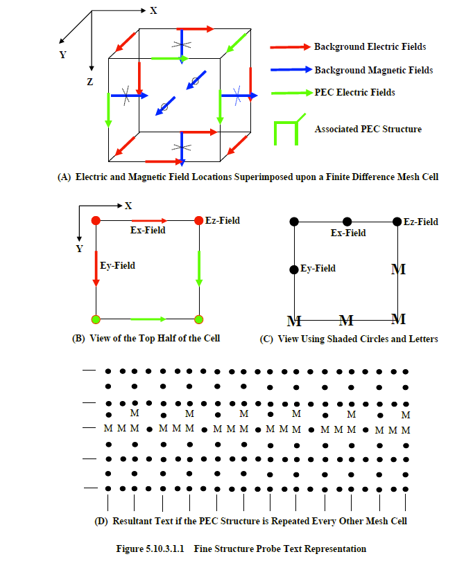
EMA3D® input file is desired.The electric and magnetic field components superimposed upon a finite difference mesh cell are shown in Figure 5.10.3.1.1A. There are two types of color-coded electric fields within the figure. One color (RED) represents a field existing within the background material. The other color (GREEN) represents a field in a PEC material. This particular mesh represents the associated PEC structure depicted in the figure. If an observer were to view the top half of this cell, in the direction of the z-coordinate axis without the magnetic field vectors, then the picture of Figure 5.10.3.1.1B would be seen. The fields within this figure (x, y, and z-coordinates) all possess the same z-coordinate finite difference index. Since the electric field components all possess unique positions upon the lattice, each can be represented by a shaded circle placed at the respective locations – the location being the determining factor for identifying a particular electric field component. Furthermore, the color of the background fields can be represented by the color black, and all PEC material field components can be coded with a letter placed at the proper location, as shown in Figure 5.10.3.1.1C. In the figure, the letter, “M”, represents a PEC material. If the lines in Figure 5.10.3.1.1C were removed, and the PEC structure repeated every other cell in the x-direction, then the picture of Figure 5.10.3.1.1D would result. This is the format of the text generated by the Fine Structure Probe. The same procedure is used for any view along any coordinate direction.
Within the Fine Structure Probe algorithm is the ability to select the rectilinear region in which to view the structure. However, this region will always be automatically reduced to encompass only the nonbackground materials within the selected region. Therefore, if a rectilinear region, bounded by the points, (0.0, 0.0, 0.0) and (10.0, 10.0, 10.0), were selected, but material existed only within the region bounded by the points, (3.0, 3.0, 2.0) and (8.0, 8.0, 9.0), then the Fine Structure Probe output would contain only the information associated with this latter region.
For a Fine Structure Probe output file, the characters, “fsp”, are concatenated onto the end of the input file base name. These particular characters are designed to abbreviate the Fine Structure Probe utility. The file extension of all Fine Structure Probe output files is, “.txt”. Thus, if the input file name was, “Model1.emin”, then any Fine Structure Probe specification will result in at least one file with the name:
“Model1fsp*.dat”
The remaining asterisk is a place-holder for an integer that numbers the files. Each Fine Structure Probe specification increments this number by one. The numbers correspond to the order of appearance of each Fine Structure Probe specification in the EMA3D input file. Therefore, if four Fine Structure Probes were specified, then four files with the following names would be created.
“Model1fsp1.dat” “Model1fsp2.dat” “Model1fsp3.dat” “Model1fsp4.dat”
EMA3D - © 2026 EMA, Inc. Unauthorized use, distribution, or duplication is prohibited.