Thin Wires |
The thin wire formalism allows the incorporation of thin cylindrical lines with diameters too small to be directly resolved by the finite difference mesh. The basic principle of the formalism involves a transmission line model referenced to the lattice cell boundaries containing the wire. The thin wires can be resistive, inductive, and terminated by an RL series circuit. The presence of the wires is realized in the finite difference code by adjusting the electric fields that lie along the wires, in a manner that simulates the existence and resultant response of the wires. The field adjustments use the wire currents only and therefore the nature of the wires, including the terminations, is not directly communicated.
Many meshed wire segments may exist at the same location, thereby possessing identical finite difference lattice indices, but belonging to different thin wires. In other words, many thin wire segments can pass through the same finite difference cell. However, too many wires within a single cell may result in a numerical instability.
The thin wire tool was designed to be used on straight lines that align to the X, Y, or Z axis (i.e., the thin wire should never have stair-stepped mesh). If users desire thin wires that must have stair-stepped mesh, they should instead use an MHARNESS cable or make appropriate adjustments to the conductivity of isotropic lines to have similar conductivity to the desired thin wire (see the adjustment equation within the Lossy Material Modeling - Low Frequency Approximation subsection here).
For more details, see the link under Related Topics at the end of this page.
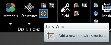
Click Thin Wire
 within the Definitions section under the EMA3D tab in the ribbon.
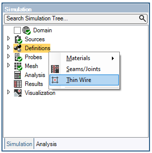
Alternatively, right click Definitions in the Simulation Tree and select
 Thin Wire.
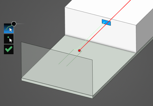
In the top left of the model window, the select line
 and select point
  tools have appeared.

Using the select line
tool, select the line to which to assign the thin wire definition. It will be immediately recolored to the color chosen in the Properties Panel.
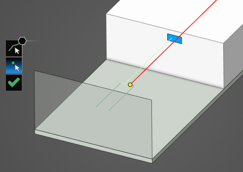
If desired, use the select point
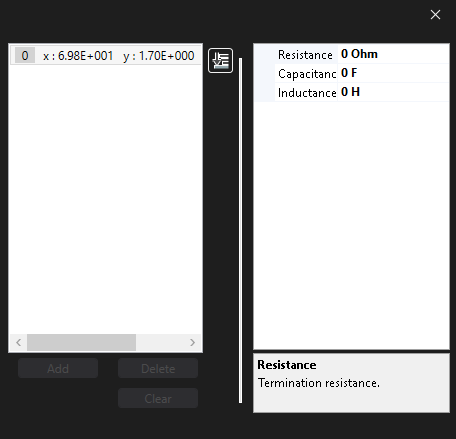
tool to select the point(s) to which to assign the thin wire terminations. They will be immediately recolored yellow. Terminations are only required if an RL circuit termination (which allows for specified resistance, capacitance, and inductance) is desired. If no terminations are defined, the thin wire is already considered to be in electrical contact with the material where the end point of the thin wire connects.
In the Properties Panel, adjust the thin wire termination point properties as desired. Clicking on the name of a property will provide an explanation of its meaning in the Properties Panel. A list of adjustable properties and their meanings is provided in the table at the bottom of this page. Clicking on Termination [#] in the Properties Panel will highlight the selected termination with a large pink dot.
Click OK
 to complete the thin wire definition.
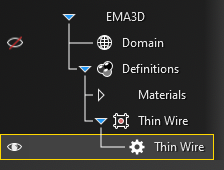
The new thin wire should now appear in the Simulation Tree under Thin Wire within the Definitions node. Selecting Thin Wire within the Simulation Tree will highlight the thin wire in the model window.
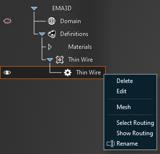
Adjust the definitions of the thin wire at any point by right clicking it within the Simulation Tree and selecting Edit from the pop-up menu. To delete a thin wire see the page on structure removal. The thin wire can also be meshed directly from the pop-up menu by selecting Mesh. Choosing Select Routing highlights the thin wire in the model window. Show Routing inverses the visibility of the model and shows only the routing of the thin wire within the model window.
Entry | Meaning |
|---|---|
Properties | |
Name | The thin wire display name |
Color | The thin wire display color |
Radius [mm] | The thin wire radius |
Resistance [Ω/m] | The thin wire resistance (thin wires are considered perfectly conducting, however, if a resistance is desired, then it may be specified through this parameter) |
Inductance [H/m] | The thin wire inductance (the inherent inductance of the thin wire is calculated automatically within the solver, however, if additional inductance is desired, then it may be specified through this parameter) |
|
|
Terminations | |
Resistance [Ω] | The termination resistance |
Capacitance [F] | The termination capacitance |
Inductance | The termination inductance |
Other Resources
EMA3D - © 2025 EMA, Inc. Unauthorized use, distribution, or duplication is prohibited.