Switches |
The switch is a feature that creates or removes a PEC connection along a line at a specified time over multiple time steps. Multiple switches are permitted in a simulation.
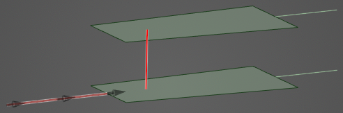
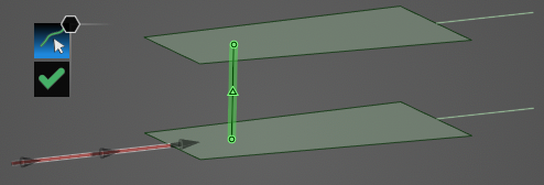
An example switch is shown below (red line).
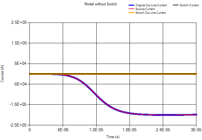
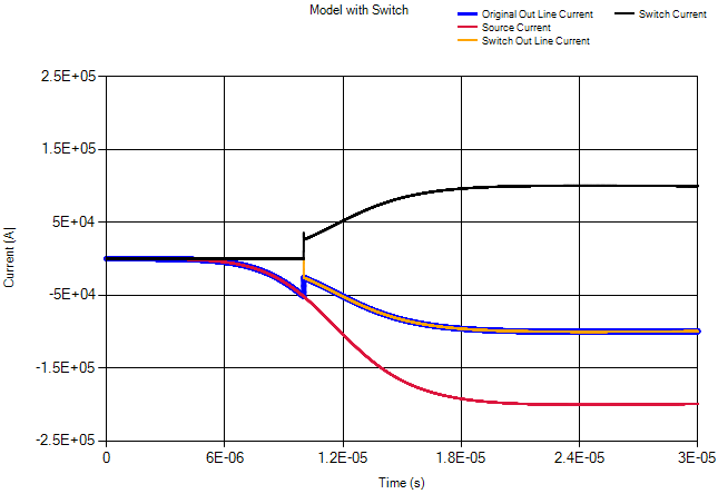
Results for a simulation without a switch (top) and with a switch (bottom) are shown below. In the no switch simulation, the top current out line has essentially zero current on it, as there is no path to that line without the switch activated. In the switch simulation, the two probes on the current out lines have equal current values once the switch has turned on (at 10 μs) and provided another path to ground.
For more details, see the link within the related topics section at the end of this page.
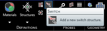
Click Switch
 within the Definitions section under the EMA3D tab in the ribbon.
In the model window, use the select line
 tool to select the line that will act as the Switch. It will glow green when hovered over and yellow once selected.
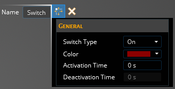
In the Properties Panel, adjust the Switch properties as desired. Clicking on the name of a property will provide an explanation of its meaning. A list of adjustable properties and their meanings is provided in the table at the bottom of this page.
Click OK
 to complete the Switch definition. The Switch will be recolored in the model window to the chosen color.
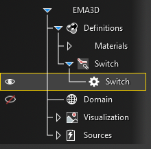
The new Switch should now appear in the Simulation Tree under Switch within the Definitions node. Selecting Switch within the Simulation Tree will highlight the Switch in the model window.
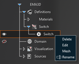
Adjust the definitions of the Switch at any point by right clicking it within the Simulation Tree and selecting Edit from the pop-up menu. To delete a Switch see the page on structure removal. The Switch can also be meshed directly from the pop-up menu by selecting Mesh.
Entry | Meaning |
|---|---|
Properties | |
Name | The switch display name |
Switch Type | Whether the switch will initially be off and turn on (On type) or be on and turn off (Off type) or turn both on/off (Dual type) |
Color | The switch display color |
Activation Time [s] | The time at which the switch is activated (the switch is turned fully on over several time steps to avoid excessive noise) |
Deactivation Time [s] | The time at which the switch is deactivated (the switch is turned fully off over several time steps to avoid excessive noise) |
Other Resources
EMA3D - © 2025 EMA, Inc. Unauthorized use, distribution, or duplication is prohibited.