Seams/Joints |
A seam/joint is an entity designed to impede the flow of current across a specified barrier according to the impedance assigned to the barrier. The impedance can be specified with resistive, inductive, and capacitive impedance components.
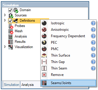
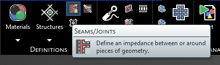
Click
 Seams / Joints within the Definitions section under the EMA3D tab in the ribbon.
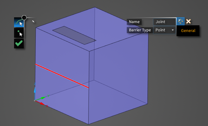
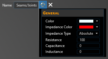
In the Properties Panel, adjust the seam / joint properties as desired.
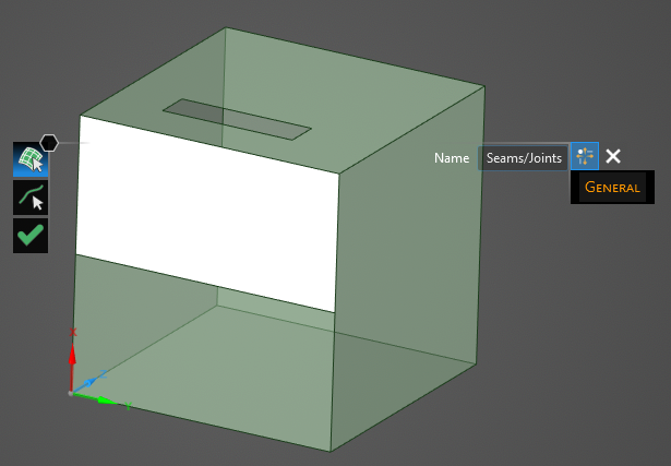
The direction of action for the seam/joint is based on the selected surface that defines the base geometry (one of the surfaces on either side of the seam/joint from which or to which current will flow). Using the select surface tool in the model window, choose this geometric surface; it will recolor to match the color chosen in the Properties Panel. Do not select both surfaces on either side of the seam/joint, as this will create two impedances and double the intended value.
The chosen base-geometry surface determines the direction of action. For example, if the surface above the seam/joint is selected as the base geometry, then the direction of action is across the seam/joint to or from that surface. If the seam/joint is assigned an impedance of 1 Ω, the current will experience a 1 Ω resistance when flowing across the seam/joint to the selected surface and when flowing across the seam/joint from the selected surface.
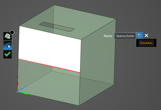
Use the select line
 tool to select the line(s) to which to assign the seam / joint definition.
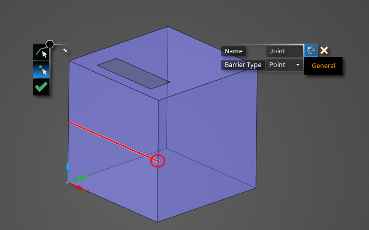
Alternatively, if you would like to create a joint at a point, select "Point" as the barrier type.
Use the select line
tool to select the line where the joint is.
Then use the Select Point
 tool to select the joint.
Click OK
 to complete the seam / joint definition.
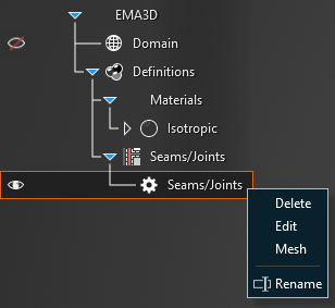
Adjust the definitions of the seam / joint at any time by right clicking it within the Simulation Tree and selecting Edit from the pop-up menu.
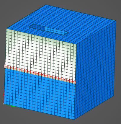
When meshed, the direction of action will be indicated by seam-colored lines across the seam / joint. At the end of the provided GIF, the meshed red lines indicate that the direction of action is in the +/- Y direction. Recall that the impedance acts in both directions across the seam / joint and users should not define it twice.
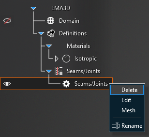
To remove a seam/joint, right click the appropriate Seam/Joint in the Simulation Tree. Select Delete in the pop-up menu.
Entry | Meaning |
|---|---|
Name | Seam / Joint name. |
Barrier Type | The barrier type. |
Entry | Meaning |
|---|---|
Color | Display color of the base geometry. |
Impedance Color | Display color of the seam / joint geometry. |
Impedance Type | Impedance specification method. |
Resistance | Resistance [Ω or Ω-m] of the impedance geometry. |
Capacitance | Capacitance [F or F-m] of the impedance geometry. |
Inductance | Inductance [H or H-m] of the impedance geometry. |
Other Resources
EMA3D – © 2026 EMA, Inc. Unauthorized use, distribution, or duplication is prohibited.