Particles and Current |
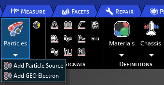
CHARGE has two options for excitations sources. The first being Particles, which has two options that are adding a GEO Electron source or default particle source. They have the same properties interface. The second being the current excitation option.
Locate the Particles option and choose between Add GEO Electron or Particle Source.
An properties menu will appear along with the Particle Source within the structure tree.
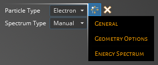
The following tables contain information on the possible parameters for General, Geometry Options, and Energy Spectrum. What is included in each subsection is determined by the Particle Type and Spectrum Type. The Particle Type can change the parameters in General, while Spectrum Type changes the parameters in Energy Spectrum. To see a full list of options for each access the drop down menu in the properties interface.
- General
Entry
Meaning
Number of Particles
Enter the number of particles used per time step used for the Particle Tracking feature
Number of Time Steps
The number of time steps the source will be active, with the time step length defined in the Domain
Atomic Number
Set the atomic number for the Ion particle source
Nucleon Number
Set the nucleon number for the Ion particle source
Charge [e]
Set the charge value for the Ion particle source
Nuclear Excitation [MeV]
Set the nuclear excitation for the Ion particle source
- Geometry Options
Source Geometry
Parameters
Boxed
Allowing for mono or bi-directionality along X, Y or Z axis:
+ X, Y, Z- True enables flux in direction, False disables
- X, Y, Z- True enables flux in direction, False disables
Cylindrical
Plane- Select the plane the source will be normal to:
Divisions- set the number of divisions to use for the cylindrical source
Spherical
Incidence Type- Select either focused or Isotropic:
Isotropic- Particles travel in all directions
Focused- Particles travel radially towards origin
Planar
Plane- Select the plane the source will be normal to
Direction- select either the + or - direction in the plane axis chosen
Charge Density
Set the Ion charge density
- Energy Spectrum
Entry
Meaning
Spectrum
Import spectrum file
Current [A/m2]
Set the current that will be used for a single time step in the spectrum file
Energy Spectrum
Set energy levels and the corrisponding fluence
Integral Flux Time [s]
Time adjustment made to the manual entry of energy bins
Spectrum Energy [MeV]
Set the energy that will be used for a single time step in the spectrum file
Satellite Name
Satellite to be imported from SKT
SKT Particle Source
Generate Particle Source from SKT data
In Sync
Has particle source been synced with SKT
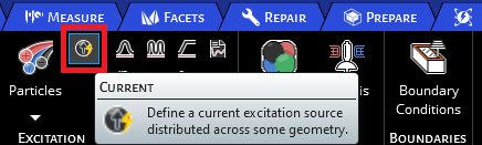
EMA3D Charge allows setting electric or magnetic current distributed across geometry as an excitation source. The locations of the current sources are specified by identifying geometry or nodes where the source is to be applied, with additional data provided to specify the source characteristics.
Click Current
 within the Excitation panel under the EMA3D Charge tab in the Ribbon.
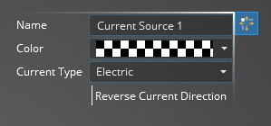
Adjust the properties of the current source in the properties panel. The list of adjustable properties and their definitions are provided in the table at the end of this page.
Click on the appropriate selection tool (i.e., surface
 , line
  , or point body
  ,) in the top left of the model window to restrict the current source assignment definition.
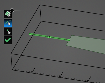
Click on the geometric entity to be excited. It will be highlighted. Note that the geometric entity used for the source should not have a material definition assigned to it.
Click OK
 to complete the current source setup.
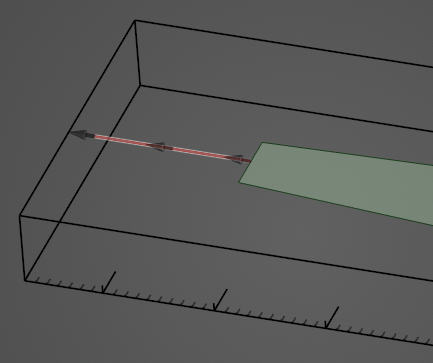
The excited geometry will be recolored in the model window (users may need to click elsewhere in the model window to remove the highlighting). Additionally, for a line source, the flow direction of the current will be denoted by gray arrows on the excited geometry.
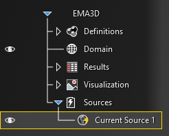
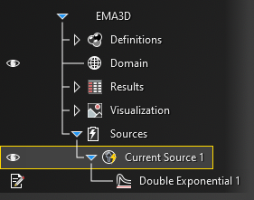
The current source will be added to the Simulation Tree under the Sources node as Current Source. The yellow warning label attached to it indicates that the source needs a signal attached to it.
Instructions on adding signals can be found here.
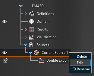
To edit the current source at any time, right click Current Source at any time in the Simulation Tree.
- Current Source Properties
Entry
Meaning
Reverse current direction
The current flow direction is prescribed automatically depending on the direction in which the geometry was drawn. The flow direction for a line will appear as gray arrows overlaid on the source geometry after clicking the OK
button. To reverse the direction change False to True
Current Type
The type of current, Electric or Magnetic, to be applied to the selected geometry
Color
The rendered color of the source in the model
Other Resources
EMA3D - © 2025 EMA, Inc. Unauthorized use, distribution, or duplication is prohibited.