Signals |
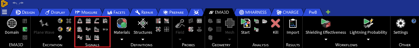
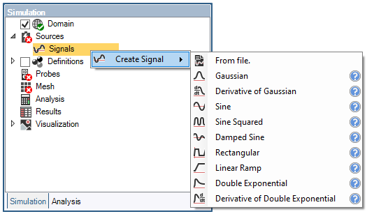
The section Signals contains the many different types of predetermined analytic waveforms supported by EMA3D. In addition to the capability to load a waveform signal from a data file, EMA3D has the following waveforms:


The buttons in this section are the same in both the EMA3D and MHARNESS panels, and users may select them under either tab.
Signal-specific information is provided in the links above, but general instructions are provided in the sections below for:
Creating and defining a signal
Editing a signal
Other signal options
Signal properties
Creating and defining a signal
Choose your desired signal in the Signals section of the ribbon.
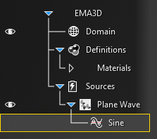
To add the signal to a source, click and hold the signal within the Signals node in the Simulation Tree and then drag and drop it on the source (e.g., on the plane wave). The signal should then be nested beneath the corresponding source.
Editing a signal
As mentioned in the prior section, the signal can be edited immediately after adding it when the signal editing window appears.
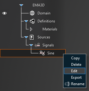
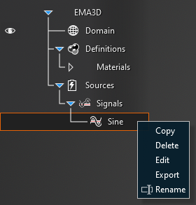
Alternatively, the signal can be edited at a later time by right clicking the signal in the Simulation Tree and selecting Edit.
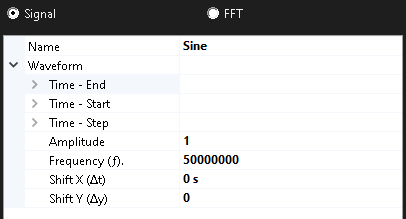
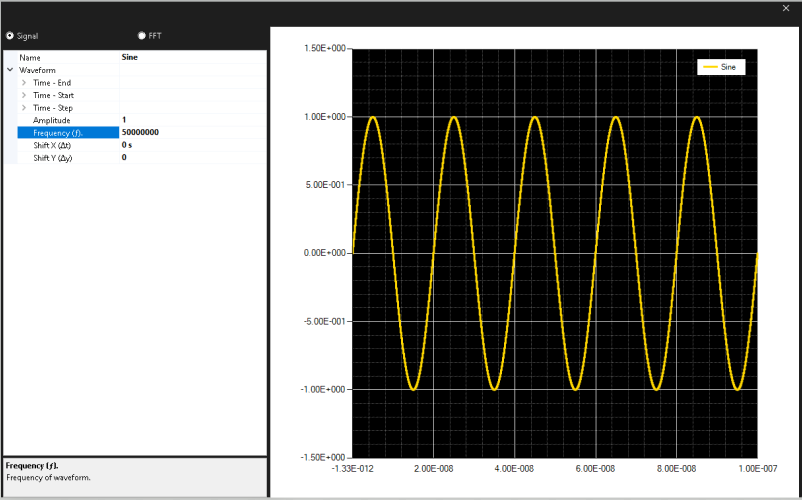
In the signal window that pops up, various parameters of the signal can be adjusted. These parameters are described in the table at the end of this page. Additionally, the frequency spectrum of the signal can be inspected by clicking FFT in the top left of the window.
To view the definitions of the variables in the GUI, click on them and a short description will appear in the bottom of the signal properties window.
Other signal options
Right click the signal in the Simulation Tree to delete, edit, rename, copy or export the waveform:
Entry | Meaning |
|---|---|
Entry (may not be applicable to all signal types) | Meaning |
Name | The display name of the signal |
Time - End [s] | The simulation time the signal turns off. The default end time matches the simulation end time. Time - End can be changed only if the field Same as simulation is set to False |
Time - Start [s] | The simulation time the signal turns on. The default start time matches the simulation start time. Time - Start can be changed only if the field Same as simulation is set to False |
Time - Step [s] | The sample rate of the signal. The default step time matches the simulation step time. Time - Step can be changed only if the field Same as simulation is set to False |
Amplitude (A) | The waveform amplitude |
Frequency (f) [Hz] | The waveform frequency |
Shift X (Δt) [s] | Shift the beginning of the waveform relative to t=0s. This parameter differs from Time - Start. In Time - Start the original signal does not change, it simply waits to turn on until the specified time. In Shift X (Δt), the signal is recalculated using the time specified in Shift X (Δt) as the new t=0s such that in the wave equation t is replaced by (t-Δt), and this signal starts immediately. So, for example, in a damped sine wave, changing Shift X (Δt) to a positive value will cause an increase in the initial amplitude as the entire wave is shifted to the right along the X axis. Note that all signals MUST start at 0 or the EMA3D simulation will provide a warning and fail when run. |
Shift Y (Δy) | Shifts the waveform amplitudes relative to 0. Note that all signals MUST start at 0 or the EMA3D simulation will provide a warning and fail when run. |
Auto-configure | Configures the waveform parameters to match the frequency selections in the computational domain |
Alpha (α) | The waveform alpha parameter |
Beta (β) | The waveform beta parameter |
Time to peak (t0) [s] | Time at which waveform reaches peak amplitude |
Duty Cycle | Fraction of period the signal is on (0.0-1.0) |
Rise Time [s] | Time for signal to reach designated high value from low value |
Fall Time [s] | Time for signal to reach designated low value from high value |
EMA3D – © 2026 EMA, Inc. Unauthorized use, distribution, or duplication is prohibited.