Surface Materials |
If you are running an surface simulation and have set the Charging Environment to Surface Charging in the Domain setup, you can now add a Surface Charging Material. Click on Materials in the Definitions section of the CHARGE tab, and click Surface Charging Material. You will have the option to use existing material definitions or define custom materials.
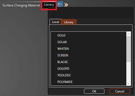
After clicking Surface Charging Material a user interface for Surface materials will appear. Click Library in the Surface Charging Material interface to open up a window with tabs to access materials in the Library. Clicking on the Library shows the list of available materials from variable resources. The materials and their properites are available in the Capabilities section: Materials. If the material you want is listed in the Library, click it to add it to the Simulation Tree. This also puts it in the Local tab of the Surface Charging Material window.
Within the properties window, clicking on the Local tab brings you to materials within the local repository. Within the local tab the user is able to add New
 materials, Copy
  materials, or Delete
  materials within the local repository.
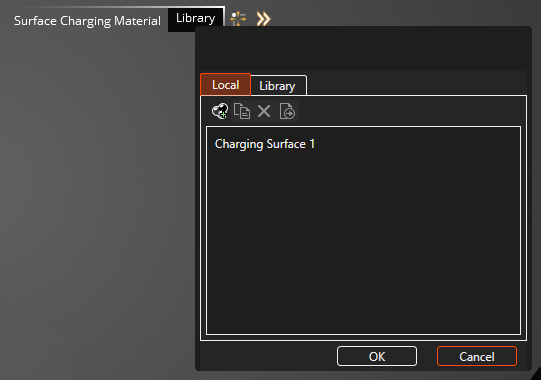
Click on the New
material button to add a generic 'Charging Surface 1' material to the Local list. Click this to add it to the Simulation Tree. Refer to the image above.
With either a new or library material added to the simulation tree, you can now investigate the properties that describe the material.
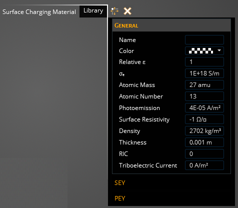
The tables below shows all the material properties used and their description.
- General
Property
Description
Color
Allows the user to assign a specific color to the material
Name
Allows the user to designate a name to the material
Relative permittivity
Material dielectric constant used for quasi-static and full-wave solutions (1 for metals)
Bulk conductivity [S/m]
Material electric conductivity, value of -1 can be used for perfect conductors and numerical stability
Atomic mass [amu]
Average atomic mass of material in amu
Atomic number
Atomic number of the material
Photoemission [A/m2]
Release of electrons from a material when exposed to EM radiation
Surface resistivity [Ohm/square]
Material current resistivity at the surface, value of -1 can be used for perfect conductors
Density [kg/m3]
Material volumetric density
RIC
Radiation induced conductivity
Thickness [mm]
Assigned thickness for material used
Triboelectric Current [A/m2]
Current density produced due to vibrational effects
SEY-Secondary electron yield of the material. If using the bi-exponent range law form assigned in the Domain setup, it uses the following electron range formula.
R 1 * E e 1 + R 2 * E e 2 :SEYProperty
Description
Delta max
Maximum SEY for electron impact at normal incidence
E-max [ke]
Primary electron energy to produce maximum yield at normal incidence
Range 1
R1 of the Bi-exponent range equation above
Exponent 1
e1 of the Bi-exponent range equation above
Range 2
R2 of the Bi-exponent range equation above
Exponent 2
e1 of the Bi-exponent range equation above
PEY-Proton Electron Yield:
PEYProperty
Description
Proton yield
Secondary electron yield for normal incident 1keV protons
Proton max [keV]
Proton energy to produce maximum secondary electron yield
Filling in these material properties can be daunting and have a large influence on the outcome of the simulation. Often approximations or estimates are used for certain parameters, and tweaking of material properties is always of interest to see how it affects the output data.
Once you are satisfied with the material parameter you have set, you will need to assign the material to the appropriate surfaces of the model. In the top left window make sure
 tool is selected and go through the model and select all the applicable surfaces with your cursor. As you do so, they will change color to the color you assigned the material, indicating it has been assigned to that surface.
Once you have selected all of the surfaces you want assigned to this material, press the Complete
 button to finalize the assignments.
The user will see the material they've created in the structure tree and can deselect it here to toggle the color visualization of it on the model. Additional materials can be added to the tree and assigned to the model. Once the model has been fully assigned with material, then the user can go to the meshing portion of the simulation set up.
EMA3D - © 2026 EMA, Inc. Unauthorized use, distribution, or duplication is prohibited.