Lattice |
MHARNESS is based on an FDTD method suitable to solve Maxwell's equations in a finite solution volume. In MHARNESS, the solution volume is denoted as Lattice.
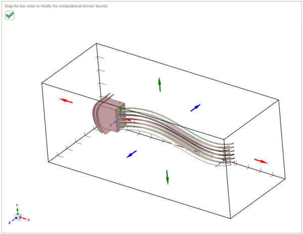
The Lattice is a parallelepiped on whose faces the boundary conditions are applied. The dimensions of the lattice, along with the three Cartesian directions, are affected by the boundary conditions. The proper distance to place the boundaries from the object being modeled depends upon the finite difference boundary condition used.
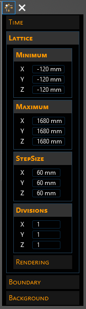
The domain lattice settings can be set within the domain Properties Panel under Lattice.
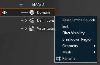
To access the Lattice properties, right click Domain in the Simulation Tree and select Edit.
Then scroll down the Properties Panel to Lattice.
The geometrical dimensions of the simulation lattice can be assigned by editing the Minimum and Maximum sections in the Properties Panel or by dragging the six directional handles in the model window. By default, the domain lattice encapsulates the model geometry when  Domain is first selected.
Entry | Meaning |
|---|---|
Minimum [mm] | The minimum spatial bounds (X, Y, Z) of lattice coordinates |
Maximum [mm] | The maximum spatial bounds (X, Y, Z) of lattice coordinates |
Step Size [mm] | The mesh cell dimensions along the three Cartesian axes (X, Y, Z). The default mesh size is automatically calculated by MHARNESS based on the time settings, to which the cell dimensions are related through the Courant Condition. Therefore, changing the Step Size may change the time settings, as necessary. Note that for simulations containing MHARNESS cables, the Step Size must be the same for all axes. Simulations without MHARNESS cables can have different Step Sizes. |
Parallel Divisions | The number of cores for each Cartesian direction (X, Y, Z) to be used for the solution process. The total number of solution cores is obtained by multiplying the three numbers together. For improved performance, cores should be distributed based on the number of mesh cells along each axis. For example, for an 8-core computer, a simulation with 100 cells in X, 200 in Y, and 300 in Z would reasonably have parallel divisions set to (1 , 2, 3). For best computational performance, it is recommended that no more than ~90% of the total computer cores be used. |
Other Resources
EMA3D - © 2025 EMA, Inc. Unauthorized use, distribution, or duplication is prohibited.