Mesh Settings |
Mesh settings is the section that allows the user modify the resolution and tessellation of the mesh engine.
This section discusses setting the properties for the Global Mesh settings, which is applied to the model in its entirety. Its not until a Mesh Group is created that these will override the Global Mesh settings.
In the Meshing section of CHARGE, click on Mesh Settings
 and select Edit Global Settings.
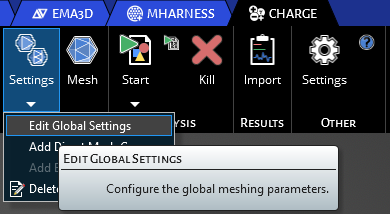
The Properties window will appear for the mesh settings. Clicking the Advanced Mesh Options allows you to see all the options for the meshing configuration.
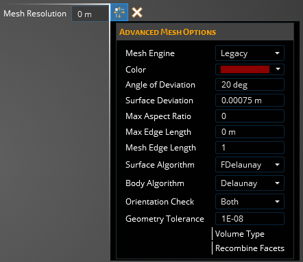
The main parameter concerned by the user is Mesh Resolution (m), which generally sets a cell length constraint by this value and has the greatest influence on the sizing of the mesh cells. Choosing a low value for resolution will generate many cells within you model, producing more physically accurate results but at the cost of solving time and computational resources. You will want to gauge the size of your overall model and pick a resolution size that will generate a decent number of cells per surface or volume, but not an enormous amount so that your computer will struggle with the meshing operation. It is best to start with a larger value and see how well the computer handles the meshing and then work your way down to a realistic number that gives good results within a decent computation time.
The Advanced Meshing Options can be seperated into 3 differente catagories: Advanced Mesh Engine Options (are largely unaltered by the user), Discovery Tessellation Options (allows greater control of the mesh configuration), and Other:
Advanced Mesh OptionsProperty
Description
Discovery Tessellation Options
Angle of Deviation Sets the angle deviation for the inital Discovery facets
Surface Deviation
Sets the maximum surface deviation for the initial Discovery facets
Max Aspect Ratio
Sets the maximum aspect ratio for the initial Discovery facets
Max Edge Length [m]
Sets the maximum edge length for the initial Discovery facets
Advanced Mesh Engine Options
Mesh Edge Length [m]
The maximum edge length adjustment for the mesh engine
Surface Algorithm
The algorithm used in the mesh engine for surface
MeshAdapt
Automatic
Initial
Delaunay
FDelaunay
BAMG
FDelaunayQuad
PackParallel
Body Algorithm
The algorithm used in the mesh engine for solid bodies
Delaunay
Initial
Frontal
MMG3D
RTree
HXT
Orientation Check
Descides of the mesh engine should check the initial, final, both or non of the node orientations
None
Initial
Both
Other
Geometry Tolerance
...
Volume Type
...
Recombine Facets
...
Mesh Engine
Legacy
Discovery
Color
Define the color of the mesh
With the Mesh Settings chosen, the user can finalize them by clicking the Complete
 button in the top left corner of the model window. Since this is the Global mesh group the user does not assign these settings to specific surfaces or bodies.
The user can continue on to the Mesh Operation section in the link below to allow the mesh engine to mesh the geometry. If a Mesh Group is wanted, continue to the Add Mesh Group section
This section discusses creating and setting the properties for a Mesh Group, which can be applied to specific surfaces or bodies of the model, allowing variable meshing of the geometry. When a Mesh Group is created, its settings will override those of the Global settings. Multiple Mesh Groups can be used if needed.
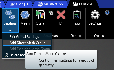
In the Meshing section of CHARGE, click on Mesh Settings
and select Add Mesh Group.
The Properties window will appear for the mesh settings. You are able to adjust the Color and Mesh Resolution [m]
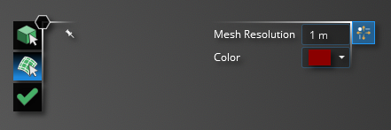
The only difference from the Global Mesh settings is that the user can now assign these mesh settings to either a surface or body. In the top left corner you will see a Select Body
 tool, a Select Surface
  tool and a Complete button.

If you are doing an internal simulation, select the Select Body
tool, and using your cursor, select the bodies of your model you want to have the Mesh Group settings applied.If you are doing a surface simulation, select the Select Surface
tool, and using your cursor, select the surfaces you want to have the Mesh Group settings applied to.
Once you have selected either the surfaces or bodies you want assigned to the Mesh Group, press the Complete
button to finalize the assignments.
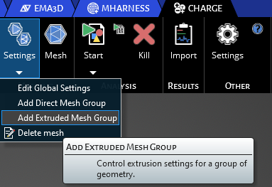
Control extrusion settings for a group of geometry. This function can be accessed for internal charging domains only. The following instructions will walk through how to define and assign a extruded mesh group to geometry.
Click Add Extruded Mesh Group under Settings in Meshing.
An interface will appear where the user can customize the meshing. This is where you will set the mesh resolution, color, and subdivisions along a specific geometry.
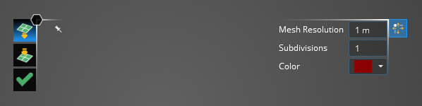
Click on one surface of your geometry then click on the icon with the arrow pointed into the plane on the left hand side of the interface. Click another surface that you want to extend the mesh too. After specifying the other paramters click the check mark.
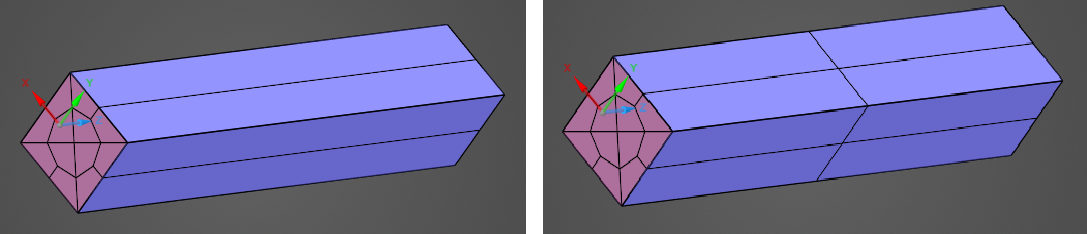
Visuals after the meshing steps are shown below. Both images are with 1m mesh resolutions but the left image has subdivisions set to 1 while it is equal to 2 for the right image.
Now that all the mesh settings are set, you can do the actual Mesh Operation.
Mesh
EMA3D - © 2025 EMA, Inc. Unauthorized use, distribution, or duplication is prohibited.