Frequency Dependent |
There are three keywords associated with frequency dependent materials. The keywords are listed below:
FREQUENCY DEPENDENT BODY
FREQUENCY DEPENDENT SURFACE
FREQUENCY DEPENDENT LINE
Frequency dependent materials in
EMA3D® are always electromagnetically isotropic and linear. Both electric and magnetic frequency dependent materials are allowed. Frequency dependent materials are characterized by the static conductivity ( σ0), the infinite frequency permittivity ( ε∞), the infinite frequency permeability ( μ∞), and the static magnetic conductivity ( σm0), along with the sum of any number of first and second order rational functions. Utilizing complex expressions for the relative permittivity, ε(ω), and the relative permeability, μ(ω), frequency dependent materials can be characterized by: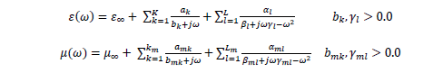
The definition and acceptable range of parameters is provided below.
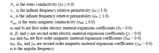
Assigning values outside of the range given will result in an error message and program termination. In addition, the real part of the above permittivity and permeability characterizations must be greater than 1.0 for all frequencies resolvable by the finite difference code.
It is the responsibility of the user to determine the coefficients and the number of functions in each representation above. A GUI tool is provided to aid in this endeavor. If frequency dependent materials overlap, then the last one defined, meaning the last one read in from the EMA3D input file, takes precedence. The region of overlap will therefore be redefined to possess the electromagnetic parameters of the last frequency dependent material encountered.
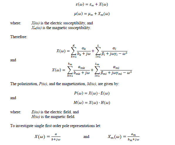
The above characterizations of the complex relative permittivity and relative permeability can be used to approximate or curve-fit complex frequency dependent material behavior requiring numerous first and second order pole descriptions. However, many materials can be adequately represented using one first-order pole or one second-order pole. It is thus instructive to understand the physics associated with such descriptions. The complex relative permittivity and relative permeability in the above equations can be expressed as:
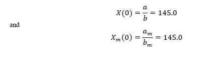
A plot of these susceptibilities is given in Figure 5.7.3.1A for the parameter values supplied in the figure. The DC values, X(0) and Xm(0), are given by the following equations with the numeric values derived from the parameter values supplied:
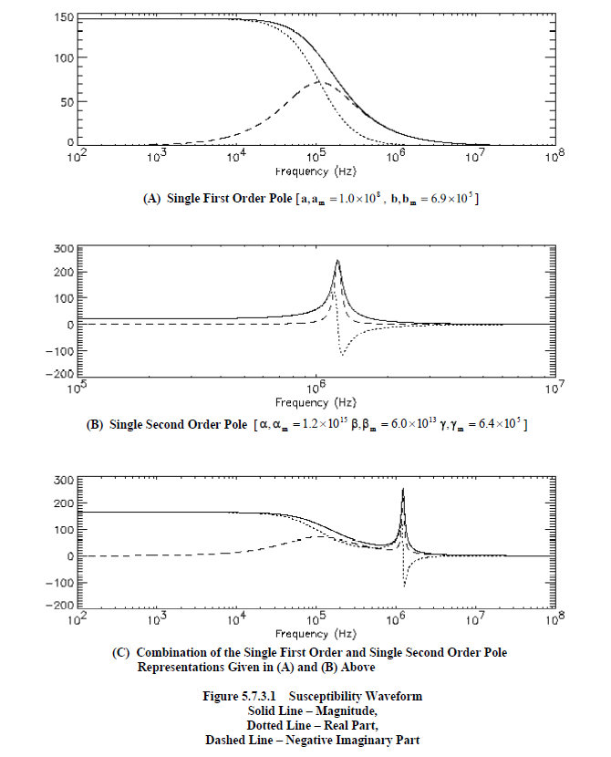
A single pole representation can be used to describe thermal effects that tend to randomly distribute the orientation of electric and magnetic molecular dipoles. For instance, if
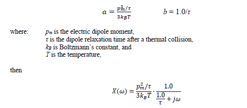
If the period of the frequency, ω, is much larger than the relaxation time, τ (ω 1/τ), then the material can polarize with the frequency of the electric field. If, however, the period of the frequency, ω, is much smaller than the relaxation time, τ (ω 1/τ), then the material can no longer polarize, because of thermal effects, and the susceptibility goes to zero. This type of behavior is seen in Figure 5.7.3.1A.
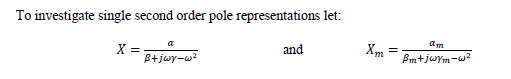
A plot of these representations is given in Figure 5.7.3.1B for the parameter values supplied in the figure. Inspection of this plot shows a resonant point. These representations can be used to describe molecular polarization and magnetization in terms of a simple harmonic oscillator with a damping term. For instance, if

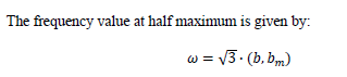
If, ω0 >> γ2, and it usually is, then the full width at half maximum is given by, 2γ. The DC value, Xm(0), and the peak value, Xm(ωp), are given by the following expressions, with the numeric values derived from the parameter values supplied in Figure 5.7.3.1B:
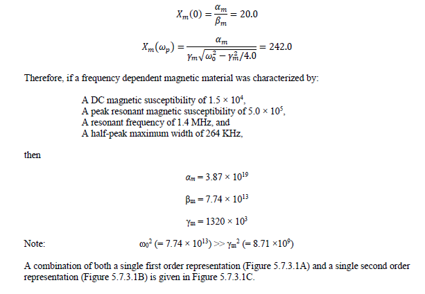
EMA3D - © 2026 EMA, Inc. Unauthorized use, distribution, or duplication is prohibited.