Cylindrical Conductors |
There is only one keyword associated with cylindrical conductors. This keyword is provided below.
• CYLINDRICAL CONDUCTOR
The cylindrical conductor algorithm allows the incorporation of conductors, of any radius, to be placed within the finite difference mesh. Whereas thin wires must possess a diameter smaller, and preferably much smaller, than the smallest finite difference cell, in the cross-sectional directions, cylindrical conductors can possess any diameter. This includes diameters too small to be directly resolved by the finite difference mesh, as with thin wires, up to a those spanning across many finite difference cells. However, unlike thin wires, cylindrical conductors can only be employed when using a cubic mesh.
Cylindrical conductors can be resistive, inductive, and terminated in an RL series circuit. These conductors use the finite difference electric fields as drivers. The presence of cylindrical conductors is realized in the finite difference code by adjusting the electric fields that lie along the conductors in a manner that simulates the existence and resultant response of the conductors. The field adjustments use the conductor currents only and therefore the nature of the conductors, including the terminations, is not directly communicated.
Unlike thin wires, only one cylindrical conductor can exist at any single location. If this is violated, then an error message will result and
EMA3D® will terminate.There are many user-selected features associated with cylindrical conductors as listed below.
• Presence of insulating dielectric jacket (thickness and permittivity) • Radius () • Resistance per unit length () • Inductance per unit length () • Current sources • Voltage sources • Circuit terminations • Junction terminations • Packing factor
A cylindrical conductor can be specified with an outer insulating dielectric jacket. If insulation is desired, then the insulation radius and permittivity must be provided. A bare cylindrical conductor is always electrically connected to surrounding material. However, if a cylindrical conductor is specified with a dielectric insulating jacket, then the conductor is insulated from the material in which it is immersed, except at the conductor endpoints. A cylindrical conductor with insulation may therefore, still be terminated at the end points and/or conductively connected to existing material at those endpoint locations.
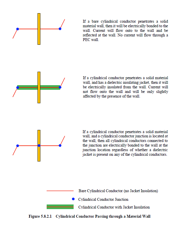
If a bare cylindrical conductor passes through a material wall, as shown in the first diagram of Figure 5.8.2.1, then it will be electrically connected or bonded to the material wall. Current on the cylindrical conductor will flow directly onto the material wall. If the material wall is PEC or PMC, then a warning message will be issued. The result of such a configuration is zero current and voltage responses within the wall, thereby shorting the conductor to the PEC or PMC material at those locations.
If the cylindrical conductor is specified with a dielectric jacket, then the conductor is electrically insulated from the wall, as seen in the second diagram of Figure 5.8.2.1. The current on the conductor will therefore pass through the wall nearly unimpeded. The only effect being a change in the conductor impedance at the location of the wall material.
However, if a cylindrical conductor junction exists at the wall, as seen in the third diagram of Figure 5.8.2.1, then all cylindrical conductors connected to the junction are electrically bonded to the wall at the junction location regardless of whether dielectric jackets are specified.
A cylindrical conductor can be assigned any radius. A radius of zero will effectively remove the cylindrical conductor from the problem.
Cylindrical conductors are considered perfectly conducting. However, if a resistance is desired, then one may be specified through the resistance per unit length parameter, where the length unit is the meter. All cylindrical conductors possess an inherent capacitance and inductance associated with the geometry and the electromagnetic parameters of the surrounding material. However, if additional inductance is desire, such as that associated with lumped inductor circuit elements, then additional inductance can be specified through the inductance per unit length parameter, where the length unit is the meter.
Cylindrical conductors can be terminated in simple RL series circuits, in the same manner as thin wires. These configurations are shown in Figure 5.8.2.2A. Within the circuit diagrams is the material impedance parameter, Zm. This parameter is associated with the material in which the cylindrical conductor is terminated. The material impedance parameters are automatically computed. However, there are some material types that cylindrical conductors cannot be embedded in or terminated on (see Restrictions below).
The last cylindrical conductor voltage location is indicated in the diagrams. The circuit termination resistance and inductance are installed in the last finite difference cell, at the current location before the voltage termination, and is put in series with the inherent inductance and any specified lumped resistance or inductance.
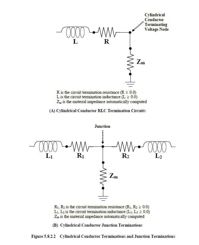
As indicated in the circuit diagrams, a ground is present. This ground is separated from the termination circuit by the material impedance, Zm. The implications of this configuration should be understood. If the cylindrical conductor was terminated in air, then Zm is effectively infinite in value. If a termination circuit was specified at this termination point, then the values of the circuit termination impedances (resistance or inductance) are, to a large extent, irrelevant. Small or large specified values are masked by the large magnitude of the material impedance. As a result, it is impossible to terminate cylindrical conductors in air with an effective overall impedance of zero. This is advantageous because such a configuration provides a contradictory definition of the cylindrical conductor in the finite difference code. An overall termination impedance of zero implies a grounded conductor. Within the finite difference code, however, the cylindrical conductor is terminated in air and ungrounded.
If the cylindrical conductor were terminated on a PEC material, then the material impedance is zero and all circuit parameters become relevant. The ground depicted within the circuits of Figure 5.8.2.2A should not be interpreted, in the traditional circuit sense, as a circuit ground, but a bond to the surrounding material at the termination end of the cylindrical conductor.
Cylindrical conductors can also be terminated in a junction. A cylindrical conductor junction is so termed, when one conductor is connected to another. Simple RL series circuit terminations can also be applied to cylindrical conductors ending in junctions. The circuit termination at junctions, are interpreted in roughly the same way as those of a single conductor termination. The termination circuit for junctions is shown in Figure 5.8.2.2B.
If a cylindrical conductor is defined with a length equal to one mesh cell increment, then such conductors will always be assumed positively directed – that is, the current within the conductor segment will be positive if flowing in a positive coordinate direction.
Cylindrical conductors may be driven with current and voltage sources. The current source is an infinite impedance source and sets the current at the location of the source equal to the source value.
The packing factor is discussed in a separate section below.
Cylindrical conductors are associated with sets of geometric lines in the EMA3D GUI. However, a geometric line is a one-dimensional entity. As long as the radius is small (much less than the finite difference cell dimension in the cross-sectional direction), the cylindrical conductor is represented by a single meshed line. However, as the radius increases, the cylindrical conductor will encounter neighboring cells. This results in a three-dimensional character with associated consequences not particularly obvious by inspection of the relevant geometric line.
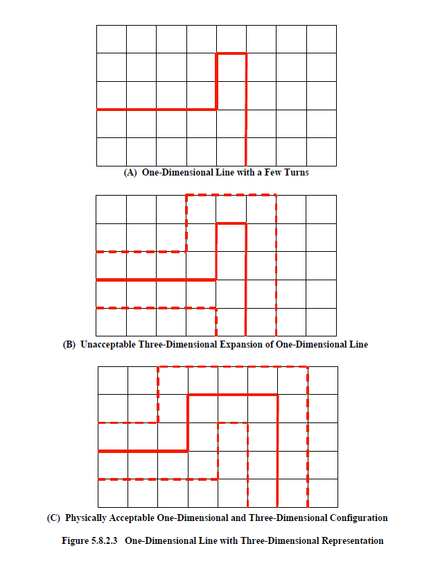
There are certain topologies that a one-dimensional line can assume that are not possible in a three-dimensional sense (i.e. when the conductor radius increases). One such configuration is shown in Figure 5.8.2.3A. Within this figure is a line, depicted as solid red, that is superimposed upon a finite difference cubic mesh. The line makes a few turns and then continues onward. If the radius was to increase, thereby encountering neighboring cells, then the corresponding three-dimensional geometric representation would be impossible to achieve, as shown in Figure 5.8.2.3B. The conductor would expand into itself which would be physically impossible. If this were to occur in the defining problem, then an error message would be produce in EMA3D and the program terminated. A more realizable situation is shown in Figure 5.8.3.3C. Expanding the one-dimensional line in this figure into neighboring cells results in a physically realizable three-dimensional configuration.
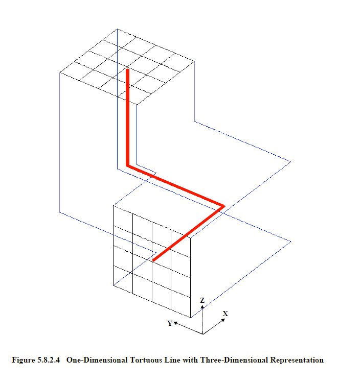
Another common topology is shown in Figure 5.8.2.4. Here a conductor line, colored red, starts in the x-coordinate direction, turns to the y-coordinate direction, and then to the z-coordinate direction. A superimposed mesh is shown at both ends of the conductor line. Assume this conductor was assigned a radius so that it was bounded, in a cross-sectional sense, by the blue lines. If the conductor was modified so that the length of the line segment in the y-coordinate direction was decreased to a value less than the conductor diameter, then the line segment in the z-direction would move against the segment in the x-direction. This would crimp the conductor in a physically unrealizable manner. If this were to occur in the defining problem, then an error message would be produced, and the program terminated.
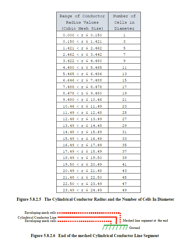
To assess the resultant topology requires knowledge of the finite difference cells enveloped as a function of the assigned conductor radius. Cylindrical conductors can only be used when a cubic mesh is employed. This is to effect proper connection among all mesh cells. For this reason, the conductor radius can be expressed in terms of the cubic mesh size. The range of cable radii and the resultant number of required cells in diameter is shown in the table of Figure 5.8.2.5.
PEC end caps are installed on the ends of all cylindrical conductors that span across multiple cells. If the cylindrical conductor depicted in Figure 5.8.2.4 was the entire conductor, from beginning to end, then the mesh observed on both ends would be PEC material. This is done to conductively bond all finite difference cells within the line at either end, as required. The end caps can be observed using the proper keywords in the Structure Probe (see Section 5.10.5.1), the Picture Probe (see Section 5.10.5.2), and the Slice Probe (see Section 5.10.5.3).
The mesh of the line segment at the end of all cylindrical conductors must be in one coordinate direction only, for a distance at least one cell longer than the conductor radius. This is required to effect proper topology and ground to materials, as shown in Figure 5.8.3.6.
Cylindrical conductors can possess radii that expand over many finite difference cells. For radii with values much smaller than the inherent finite difference cell dimension, the conductor is totally contained, in a cross-sectional sense, within a single cell. However, as the radius increases, the conductor will expand into neighboring cells thereby requiring more cross-sectional cells for accurate modeling. If the conductor is contained within a confined physical space, then this expansion may prove cumbersome if extensive geometry modifications are required to accommodate the conductor. It may prove beneficial to have the option of packing the conductor into a tighter space, even if such packing impacts accuracy (to an acceptable degree) of the numerical simulation.
Within EMA3D is a packing factor variable that allows this activity to be done. The packing factor ranges in value from “0.3” to “0.9”. The default value is “0.4”. However, the value of,”0.3” provides the greatest degree of accuracy. As the packing factor increases, the maximum allowable cable radius before expansion into neighboring cells, increases. A table of the packing factor and the maximum associated radius in provided below.
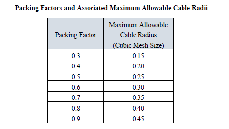
As an example, assume that a cable with a radius of 0.32 times the value of the finite difference cubic cell exists. Furthermore, assume that this cable exists in a confined space consisting of only one finite difference cell in diameter. Examination of the table in Figure 5.8.2.5 shows that this cable would require 3 finite difference cells in diameter to effect proper simulation. This is because a radisu value of 0.32 exceeds the maximum allowable radius of 0.15 that is required to fit into a single cell. The maximum value of 0.15 is associated with the default packing factor value of 0.3, as seen in the table above. However, if a packing factor of 0.7 was specified, then the maximum allowable radius would be 0.35, according to the table above, and the cable could then be packed into a single finite difference cell, in the cross-sectional direction.
There is, however, consequences of increasing the packing factor value. As this value increases, the accuracy is reduced and the possibility of a numerical instability arises. For a packing factor of “0.9”, an error upwards of 10%, or higher, is possible. However, as mentioned above, it may prove useful to trade numerical accuracy, to an acceptable degree, for the ability to tightly pack the cable into confined physical spaces. The algorithms within EMA3D are designed to detect if a numerical instability might arise, and if so, to render advice concerning actions that might be taken to avoid such an occurrence. See the EMA3D Validation Manual for a full assessment of packing factor impacts.
Cylindrical conductors possess some restrictions that thin wires do not. These restrictions are listed below.
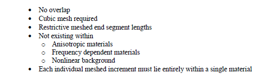
Failure to adhere to these will produce an error message within EMA3D and program termination
The first three topics were discussed above. Unlike thin wires, cylindrical conductors cannot exist within, or be terminated on, certain materials, as listed above. These materials can exist within the same finite difference problem space, however, the cylindrical conductor must not penetrate these. If this situation occurs, an error message will be produced, and the program terminated. Each individual cylindrical conductor meshed cross-sectional increment must exist entirely within a single material. That is, the cylindrical conductor cannot expand, at any location, into different materials. Failure to adhere to this will produce an error message and program termination.
EMA3D - © 2026 EMA, Inc. Unauthorized use, distribution, or duplication is prohibited.