PowerBalance |
The electromagnetic power balance (PwB) method is useful for physical situations where a volume of interest (a cavity) is excited and over-moded. Cavities become over-moded when the wavelengths of the exciting source are small compared to the dimensions of the cavity. The fields inside the cavity become statistical in this regime, which allows them to be efficiently solved by balancing incoming, outgoing, and lost power.
At high frequencies, the electric fields in illuminated cavities can reach a statistical equilibrium. At a quarter-wavelength from the wall, an equivalent power balance circuit model can be used to provide an estimate of the fields in the cavity as a function of the cavity size, aperture sizes, and the absorption cross sections (ACS) of the contents of the cavity. [1] [2] The enclosure is modeled as an equivalent circuit, shown in Figure 1.
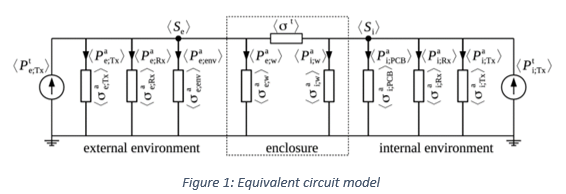
The average power densities in the environment (external) and the enclosure (internal) are denoted by 〈
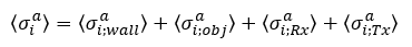
Se 〉 and 〈Si 〉. The transmission cross section of all individual apertures in the enclosure is indicated with 〈σt 〉 while the total average ACS of the contents of the enclosure is 〈The powers injected into the external and internal environments are 〈
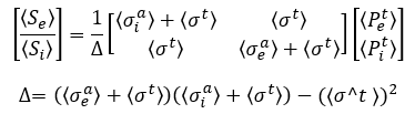
The average powers for all relevant quantities are related to the ensemble average cross section multiplied by the corresponding power density. The model of the circuit is a set of linear equations:
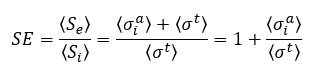
There is a special case where only a single external source illuminates a cavity with no internal sources. This is the shielding problem for a single cavity. In this case, the Shielding Effectiveness (SE) is given as:
PwB modeling presents important benefits, some of which are:
PwB methods naturally return mean, minimum and maximum bounds
No CAD cleaning or model preparation
PwB modeling is easy and approachable for new users
The solution is given instantly, and the computation effort does not depend either on the frequency range or on the size of the enclosure
Naturally, the solution is not going to be as accurate or even applicable in every possible situation. For example:
PwB theory does not provide any information about spatial distribution of fields
PwB cannot easily consider shadowing, directional radiation patterns, very under-moded problems and other effects that can greatly alter the predicted field, though there is some theoretical promise in eventually handling these effects
PwB theory cannot currently deal with energy that couples to cables and then re-radiates in enclosures, which can be the dominant factor in many aerospace cavities
The ACSs for avionics equipment and other items that fill spacecraft cavities are not currently well-characterized, so the necessary inputs for this modeling are not available for all possible systems of interest
This section of the user manual describes the procedure for preparing, solving, and post-processing the simulation using the PowerBalance tool.
The PowerBalance user interface is a ribbon-based interface as shown below:
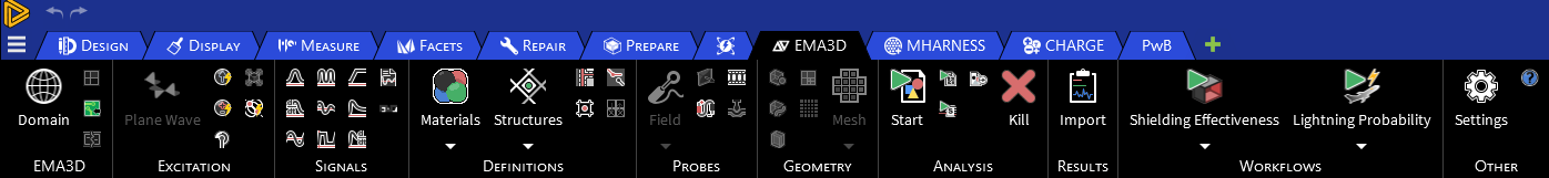
Each section corresponds to a specific stage of the PowerBalance procedure:
All the simulation data are collected in the Simulation Tree from which it can be retrieved for further editing.
References:
[1] Hill DA (2009) Electromagnetic Fields in Cavities. John Wiley & Sons, Inc., Hoboken, New Jersey.
[2] Jean-Philippe Parmantier, Isabelle Junqua and Francois Issac (ONERA) – "A network formulation of the power balance method for high-frequency coupling", Electromagnetics, vol. 25, no. 7-8, pp. 603-622, 2005.
EMA3D - © 2026 EMA, Inc. Unauthorized use, distribution, or duplication is prohibited.