Antenna Port |
The EMA3D Antenna Port tool allows users to define an antenna port for use in S-parameter simulations.
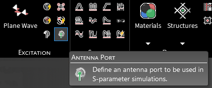
After the Domain is set, click
 Antenna Port within the Excitations section under the EMA3D tab in the ribbon.
In the Properties Panel, adjust the antenna port properties as desired.
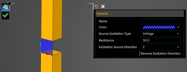
Using the select surface
 tool, select the surface to which to assign the antenna port definition. It will be immediately recolored blue.
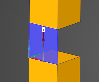
Click OK
 to complete the antenna port definition. The current or voltage source will appear on the Antenna Port surface with an arrow denoting its direction.
Adjust the definitions of the antenna port at any time by right clicking it within the Simulation Tree and selecting Edit from the pop-up menu.
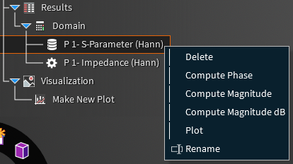
Mesh the model. To start an S-parameter simulation with the Antenna Port, select the
 S-parameter analysis button within the Analysis section under the Analysis tab within the EMA3D tab. Once complete, various analysis options are available by right clicking the S-parameter results output within the Results node of the Simulation Tree.
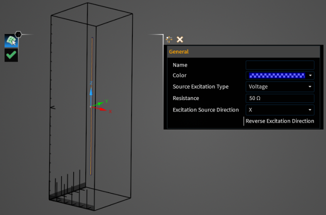
Entry | Meaning |
|---|---|
Name | Antenna Port Name. |
Color | Color to use when rendering the model. |
Source Excitation Type | Type of source excitation for the antenna port. |
Resistance | Real component of the impedance of the antenna port. |
Excitation Source Direction | Vector direction of excitation source. |
Reverse Excitation Direction | If the excitation source direction should be reversed with respect to the geometry orientation [Blue indicates True]. |
EMA3D – © 2026 EMA, Inc. Unauthorized use, distribution, or duplication is prohibited.