Thin Wires |
The thin wire formalism allows the incorporation of thin cylindrical lines with diameters too small to be directly resolved by the finite difference mesh. The formalism involves a transmission line model referenced to the lattice cell boundaries containing the wire. The thin wires can be resistive, inductive, and terminated by an RL series circuit.
Many meshed wire segments may exist at the same location, thereby possessing identical finite difference lattice indices,but belonging to different thin wires. In other words, many thin wire segments can pass through the same finite difference cell.However, too many wires within a single cell may result in a numerical instability.
The thin wire tool was designed to be used on straight lines that align to the X, Y, or Z axis (i.e., the thin wire should never have stair-stepped mesh). If users desire thin wires that must have stair-stepped mesh, they should instead use an MHARNESS cable or make appropriate adjustments to the conductivity of isotropic lines.
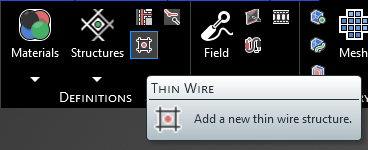
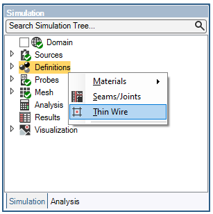
Click
 Thin Wire within the Definitions section under the EMA3D tab in the ribbon.
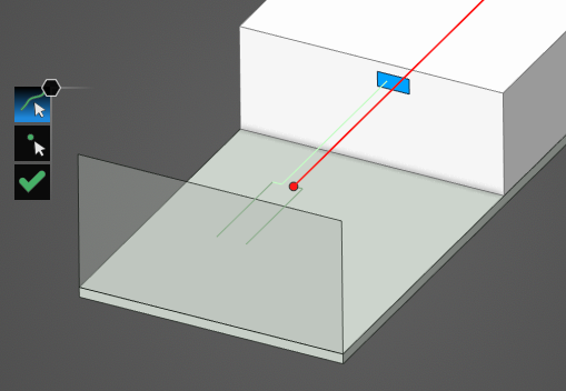
Using the select line
 select the line to which to assign the thin wire definition. It will be immediately recolored to the color chosen in the Properties Panel.
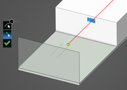
Use the select point
 tool to select the point(s) to which to assign the thin wire terminations. Terminations are only required if an RL circuit termination is desired; otherwise, the thin wire is considered to be in electrical contact with the material where the end point connects.
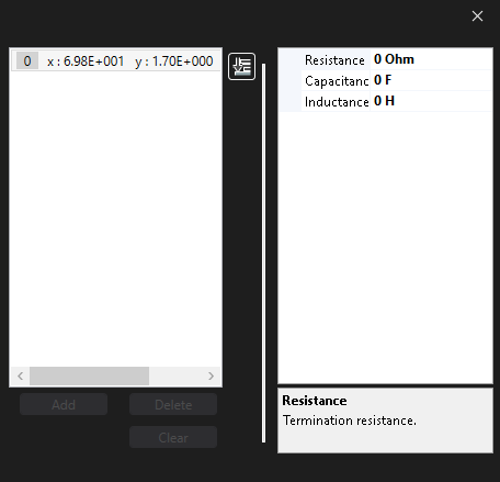
In the Properties Panel, adjust the thin wire termination point properties as desired. Clicking on Termination [#] in the Properties Panel will highlight the selected termination with a large pink dot. Adjust the terminations with the desired properties.
Click OK
 to complete the Thin Wire definition.
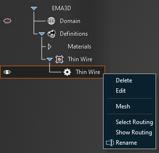
Adjust the definitions of the Thin Wire at any time by right clicking it within the Simulation Tree and selecting Edit from the pop-up menu.
Entry | Meaning |
|---|---|
Name | Name of the thin wire. |
Entry | Meaning |
|---|---|
Color | Display color of the thin wire. |
Radius | Radius [mm] of the thin wire. |
Resistance | Resistance [Ω/m] of the thin wire. |
Inductance | Inductance [H/m] of the thin wire. |
Entry | Meaning |
|---|---|
Terminations | Termination settings in the route:
|
Other Resources
EMA3D – © 2026 EMA, Inc. Unauthorized use, distribution, or duplication is prohibited.