Domain |
This part of the manual has sections that will outline the domain properties available for each of the three charging scenarios.
Click on Domain
 button in the Simulation section of the CHARGE tab.
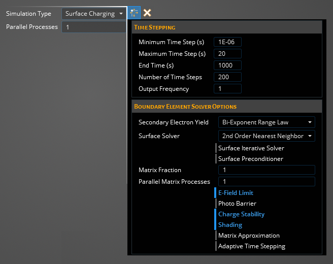
The properties window for the domain will appear, with the surface charging environment being the default shown below.

Time- Has dynamic time stepping with the following properties and descriptions:
Time SteppingEntry
Meaning
Minimum Time Step [s]
The smallest time step increment the solver can use
Maximum Time Step [s]
The largest time step increment the solver can use
Ending Time [s]
The total length of simulation time
Number of Time Steps
Total number of time steps used regardless of the length of each time step
Output Frequency
...
- Boundary Element Solver Options
Entry
Meaning
Secondary Electron Yield
The model chosen to describe the secondary electron yield interactions
Bi-Exponent Range Law
Full Reduced Extended Power Law
Surface Solver
The specific solver used which determines how the matrix is setup and solved
2nd Order Nearest Neighbor
Nearest Neighbor
Self-Capacitance Only
Standard
Surface Iterative Solver
Allows configuration of the iterative process for convergence
False-Turns off iterative approximation and greys out options
True-Turns on iterative approximation and allows writing to options
Options
Surface Maximum Iterations-Max number of iterations the solver will go through regardless of convergence
Surface Covergence Tolerance-Set the convergence tolerance for the iterative solver
Surface Interpolation Order-Set the interpolation order for the interative solver
Surface Preconditioner
Allows the preconditioner to be set for the iterative solver
Matrix Fraction
...
Parallel Matrix Processes
...
E-Field Limit
...
Photo Barrier
...
Charge Stability
...
Shading
...
Matrix Approximation
...
Adaptive Time Stepping
...
Click on Domain
 button in the Simulation section of the CHARGE tab.
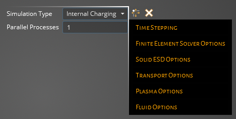
The properties window for the domain will appear. In Simulation Type select Internal Charging.

Time- Internal charging does not have dynamic time stepping, but is fixed by the user by the following:
Time SteppingEntry
Meaning
Internal Charging Time Step [s]
The length of each time step used in internal charging simulation
Number of Internal Time Steps
Total number of time steps in the internal charging simulation
Internal Output Frequency
...
- Finite Element Solver Options
Entry
Meaning
Internal Solver
Quasi-Static
Full Wave
Internal Polynomial Order
Polynomial order used for solver method
Internal Max Iterations
Max number of iterations to obtain convergence
Internal Tolerance
The allowed error to pass for convergence
Internal Preconditioner
Use of a preconditioner
Lorenz Gauge
...
Conductive Scaling
Conductive Steps-...
- Solid ESD Options
Entry
Meaning
Simulate Breakdown
Neighbor Breakdown Threshold
Intra-Breakdown Conductivity [S/m]
Post-Breakdown Conductivity [S/m]
Breakdown Time Delay [s]
- Transport Options
Entry
Meaning
Flux Bins
...
Package Selection
...
Max Tree Depth
...
Parallel Transport Processes
...
Flux
...
Transport Field Coupling
Threshold [MeV]
- Plasma Options
Entry
Meaning
Statistical Measure
...
2eV Electron Yield
...
Bias Velocity
...
- Fluids Options
Entry
Meaning
Number of Time Steps
Total number of time steps in the Fluid environment
Time Step Size
...
Output Frequency
...
Cycle Results
...
Pressure Gradient
...
Fluid Compressibility
...
Newtons Iterations
...
Import Rates
...
Joule Heating
...
Conservation
...
Model Electron Fluid
...
Click on Domain
 button in the Simulation section of the CHARGE tab.
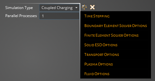
The properties window for the domain will appear. Under Charging Type in Simulation Type select Coupled Charging.

Time- Coupled charging has dynamic time stepping with the following properties and descriptions:
Time PropertiesEntry
Meaning
Time Sync
...
Now that you've setup the domain, defining the solver and time stepping, you can move onto the next step of preparing your simulation. If you are running an air breakdown simulation, you can move onto the other Simulation section feature, Breakdown Region. Alterntively if you are working with an EDB file move to the EDBImport subsection. If neither you will move onto defining your radiation sources, using either the Environment or Excitation sections depending on if you are doing a surface, internal or coupled simulation. The Environment section defines an ambient plasma and/or an illumination source that is used for either a surface or couple simulation. The Excitation section sets a particle flux that is used for either an internal or coupled simulation.
EMA3D - © 2025 EMA, Inc. Unauthorized use, distribution, or duplication is prohibited.