Magnetic Materials |
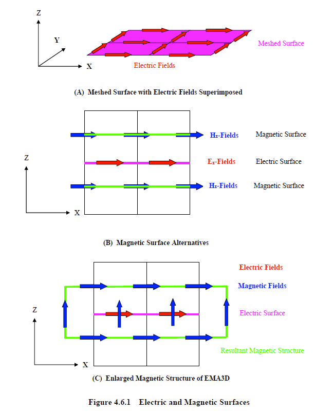
The staggered grid of the finite difference technique presents some difficulties when incorporating both electric and magnetic materials within the same computational problem. The difficulty is a consequence of the relative locations of both field types. In Figure 4.6.1A is a drawing of a meshed surface, perpendicular to the z-axis, with the finite difference lattice superimposed. The mesh convention selected places the electric fields, indicated by the red arrows, at the locations depicted - that is, parallel to, and located on, the meshed geometric surface. This convention is most favorable for the vast majority of applications, because the electric parameters (i.e. the conductivity and the permittivity) associated with a finite difference computation are linked to the electric fields and therefore exist at electric field locations. Since the electric fields are parallel to and located on the meshed geometric surface, the meshed electric material surface is identical to the meshed geometric surface.
The magnetic parameters (i.e. the permeability and the magnetic conductivity), however, exist at magnetic field locations. Therefore, if the meshed geometric surface of Figure 4.6.1A were assigned magnetic material properties, in addition to electric material properties, the former would have to be installed at magnetic field locations one half cell above or below the meshed geometric surface, as seen in Figure 4.6.1B. However, either selection is generally incorrect and would result in two disconnected surfaces – one electric and the other magnetic. Furthermore, it would be difficult to maintain connectivity of the overall magnetic structure if many surfaces are defined and the geometry is complex. Many questions of surface placement would have to be resolved such as, above or below, to the right or the left, front or back, and when to cross over the electric surface to go to the other side to maintain connectivity in other parts of the problem. To circumvent these difficulties, any structures assigned magnetic properties will effectively be enlarged to encompass the entire associated electric surface, as seen in Figure 4.6.1C. In cases involving a single uniform vacuum magnetic material over the entire structure, as in almost all cases (μ = μo, σm = 0.0), the above procedure alters nothing. The magnetic counterpart of the electric structure is enlarged but still magnetically indistinguishable from the background.
The above procedure assures connectivity of all magnetic structures and places both electric and magnetic counterparts at the same relative location. The only difficulty presented by this procedure is if very fine structures possessing magnetic parameters different from surrounding materials are modeled. If two surfaces are separated by one mesh cell and assigned both electric and magnetic parameters, different from surrounding materials, then the associated magnetic enlargement would “swell” the surfaces to within close proximity of each other. The user should be aware of this and mesh appropriately.
EMA3D - © 2026 EMA, Inc. Unauthorized use, distribution, or duplication is prohibited.