Two Dimensions |
The two-dimensional capability allows the specification of a two-dimensional slice through an existing three-dimensional model and the execution of the resulting two-dimensional finite difference approximation. The two-dimensional capability can produce numerous benefits in many cases. These benefits include insight into the electromagnetic behavior of the corresponding three-dimensional model and the possible assessment of the 3D model accuracy. A two-dimensional slice through an existing three-dimensional model executes substantially more quickly. This allows a quick observation and assessment of late time behavior. A two-dimensional model could possibly compute thousands of times faster than the corresponding three-dimensional counterpart. For a given amount of computer memory, a two-dimensional model can be meshed at significantly finer resolutions allowing the assessment of accuracy of certain aspects of the three-dimensional model.
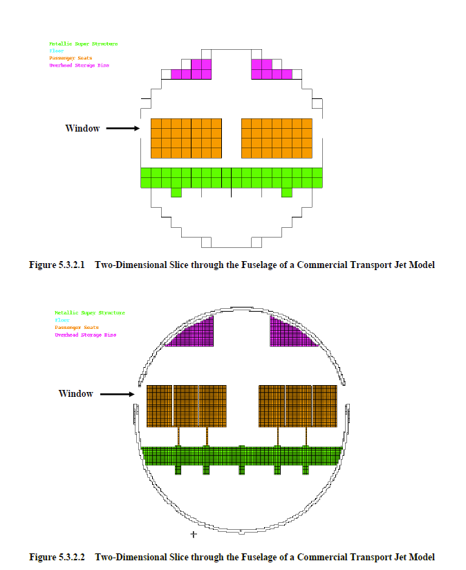
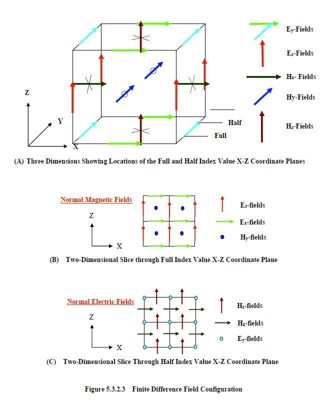
The cubic mesh of Figure 4.1 has an increment of eight inches. This model requires 92 Megabytes of computer memory for single precision applications. A two-dimensional slice through the center of the fuselage is shown in Figure 5.3.2.1. This model would have a memory requirement of approximately 16 Kilobytes for single precision applications. A corresponding model, with a one-by-one-inch square mesh, is provided in Figure 5.3.2.2. This model would have a memory requirement of approximately 1 Megabyte for single precision applications. The more finely meshed one-inch, two-dimensional model, could be used to compare electromagnetic coupling levels through the window apertures, for various frequencies, to assess the accuracy afforded by the more coarsely meshed windows of the three-dimensional model. The resolution of the two-dimensional model of Figure 5.3.2.2 allows distinction between the inner and outer fuselage skin surfaces. This model could be used if cable behavior between the walls was of interest.
If an existing input file of a three-dimensional model is edited for two-dimensional computation, then the resolution remains the same, but the model can be used to assess late time behavior because the speed of computation is significantly increased.
There are two different two-dimensional configurations for a given coordinate direction. These were shown, for the xz plane only, in Figure 3.2.1 and duplicated below in Figure 5.3.2.3. The field topology and index planes, for a three-dimensional finite difference mesh cell, are shown in Figure 5.3.2.3A. For the full index plane configuration of Figure 5.3.2.3B, the electric fields are parallel to the two-dimensional plane and the magnetic field is normal. This configuration will be referred to as the one with normal magnetic fields. For the half-index plane configuration of Figure 5.3.2.3C, the electric field is normal to the two-dimensional plane. This configuration will be referred to as the one with normal electric fields. A two-dimensional model is justified when the configuration of the source and the model are such that, in certain regions, a two-dimensional behavior closely resembles that of three dimensions. Such would be the case for the center sections of the commercial transport jet model, if the source were a plane wave incident broadside with the electric field polarized perpendicular or parallel to the fuselage.
EMA3D - © 2026 EMA, Inc. Unauthorized use, distribution, or duplication is prohibited.