Current |
The Current Probe can be used to obtain the current at any location on a cable.
Prior to defining a current probe, the cabling along the route being probed should be completed.
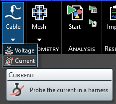
Click Probes
 within the Probes section under the MHARNESS tab in the Ribbon. Then select
  Current from the drop-down menu.
In the top left of the model window, the current probe tools will appear.
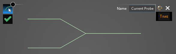
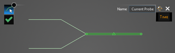
Using the Select Line
 tool, select the line on which the current probe will be placed. The line will be highlighted when selected.
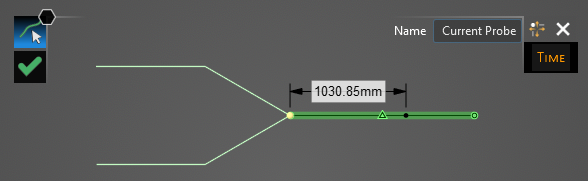
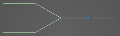
Start dragging the mouse. A placement tool will appear that states the distance between one of the segment's end points and the cursor. Click the location on the line segment where the probe will be placed. Locations not connected to the previously-selected segment will not be selectable.
A new window containing the cable cross section will appear.
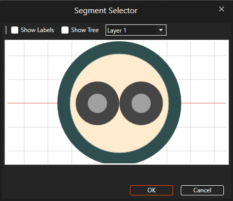
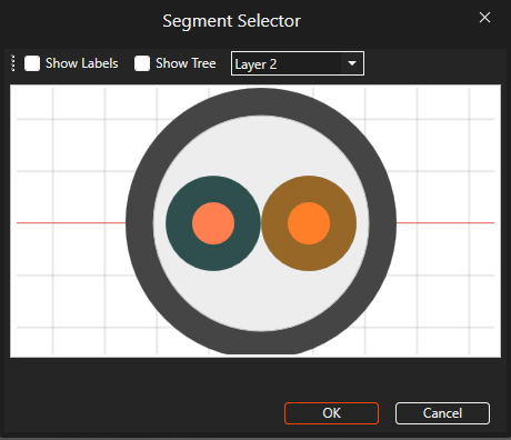
Select the cable to which the current probe should be assigned. It will glow orange once selected. Users may need to use the drop-down menu at the top of the cross section window to change between cable layers. Once selected, click OK to complete the current probe setup.
The probe location will be denoted by a blue dot in the model window. Users may need to hide the junction or segment labels to see the current probe.
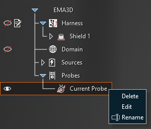
The current probe will be added to the Simulation Tree under the Probes node as Current probe.
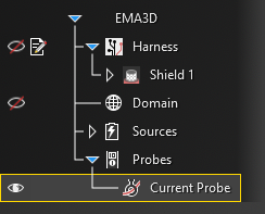
Users can delete, edit, and rename current probes in the Simulation Tree by right clicking them or double clicking them.
Entry | Meaning |
|---|---|
Start [s] | The time the probe starts recording data. The default start time matches the simulation start time. Start can be changed only if the field Match Domain is set to False (White text indicates field set to False, blue text indicates field set to True) |
Step [s] | To which domain to match the probe time step:
|
End [s] | The time the probe stops recording data. The default end time matches the simulation end time. End can be changed only if the field Same as Simulation is set to False |
EMA3D - © 2026 EMA, Inc. Unauthorized use, distribution, or duplication is prohibited.