Thin Gaps |
The
EMA3D® Thin Gap formalism allows the placement of thin gaps, thin slots, or long narrow apertures, on PEC surfaces, with gap widths too small to be directly resolved by the finite difference mesh. This can be useful when modeling such geometries as door seams, cracks, or small spaces between structures. A thin gap must exist on a topological PEC surface or an error message will result and the program terminated.A thin gap can possess any width from zero up to the size of the finite difference mesh increment in the perpendicular direction to the gap and tangent to the PEC surface. A thin gap with a zero width implies no gap at all and effectively removes the gap from the surface. The PEC surface thus remains complete and uninterrupted. A gap width equal to the finite difference mesh increment, results in the same response as if a strip of PEC material, the width of one mesh increment, was removed at the location of the gap.
Unlike thin wire segments, only one thin gap segment can exist at any location. Furthermore, thin gap segments can appear in any order within the EMA3D input file. If two segments exist at the same location, with different gap widths, then an error message will result and the program terminated.
The thin gap formalism allows the gap to contain any of the allowable materials within EMA3D, including nonlinear background media. The gap material is just that which is present in the absence of the PEC surface material at the location of the thin gap.
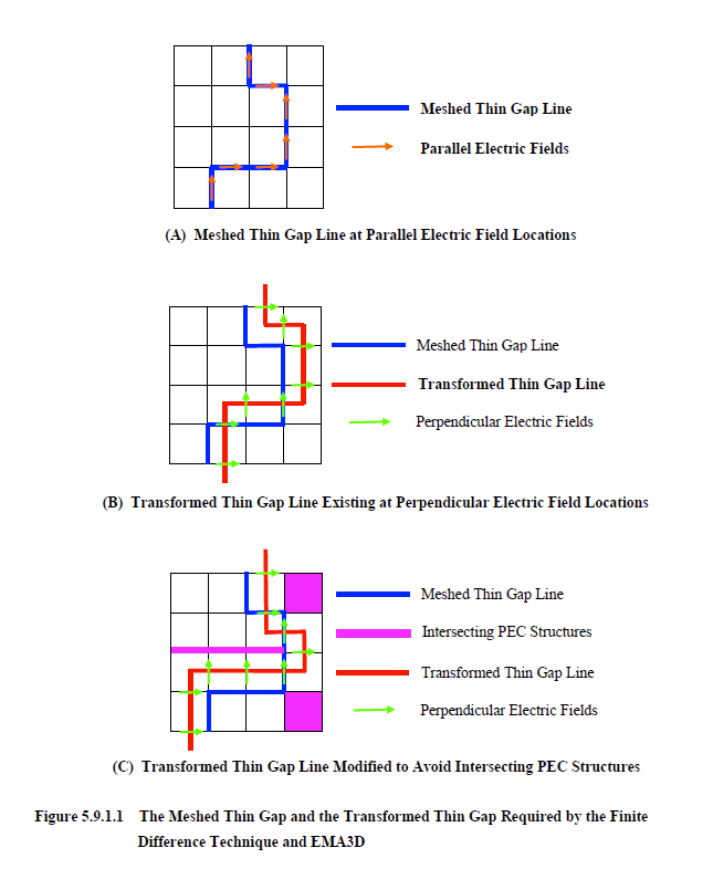
In the present EMA3D input file format the meshed thin gap exists at electric field locations. These electric fields are parallel to the meshed line. This is depicted by the orange arrows and the blue line superimposed on the flat mesh in Figure 5.9.1.1A. The flat mesh in this figure represents a meshed PEC surface. The thin gap formalism, however, operates by adjusting the electric fields that exist on a PEC surface that are perpendicular to the gap. Therefore, to implement the thin gap formalism requires a geometric translation or transformation of the gap to perpendicular field locations, as illustrated in Figure 5.9.1.2B. The transformation within the figure was achieved by translating the gap one half of a mesh increment in coordinate directions parallel to the meshed PEC surface. This is a simple case that is easily achieved. The transformation becomes more difficult if the surface has a complicated topology, in addition to other PEC structures intersecting the surface. The gap must be transformed, if possible, in a manner that avoids these structures. Intersection with such structures results in the gap being segmented which in turn, alters gap resonances and effects electromagnetic coupling through the gap. A candidate, transformed gap, that avoids some intersecting PEC structures, is shown in Figure 5.9.1C. This transformed gap is just one candidate out of many. Increased complexities in the transformation arise when the surface becomes curved with many complex intersecting PEC structures and geometries.
The above thin gap transformation is done within EMA3D. The effect of this transformation on numerical responses is insignificant in nearly all cases. However, there are some issues and configurations that may cause errors or discrepancies in defined gap geometry. One such configuration is the presence of many thin gap segments, in close proximity (within a one mesh cell distance), amidst complex surface topology and intersecting PEC structures. The EMA3D algorithm used to transform the thin gap segments may be unable to find a suitable path for all thin gaps due to intersecting structures and other gap segments existing at transformed locations. The result of this may be an incomplete transformed gap.
The above thin gap transformation is done within EMA3D. The effect of this transformation on numerical responses is insignificant in nearly all cases. However, there are some issues and configurations that may cause errors or discrepancies in defined gap geometry. One such configuration is the presence of many thin gap segments, in close proximity (within a one mesh cell distance), amidst complex surface topology and intersecting PEC structures. The EMA3D algorithm used to transform the thin gap segments may be unable to find a suitable path for all thin gaps due to intersecting structures and other gap segments existing at transformed locations. The result of this may be an incomplete transformed gap.
Another configuration of concern; is the case when no possible complete path is available for the entire transformed gap, due to the topology of the PEC surface or intersecting PEC structures. If this is the case, then the gap will be segmented at the offending locations.
EMA3D - © 2026 EMA, Inc. Unauthorized use, distribution, or duplication is prohibited.