Topological Terms |
An
MHARNESS® cable system is made up of segments, junctions, and terminations. A cable segment consists of a set of parallel conductors, each possessing a constant cylindrical cross-section and a constant inter-conductor geometric relationship throughout the length of the segment as shown in Figure 4.1.1. The inherent conductors within a segment interact through impedance matrices (capacitance, inductance, and conductance). A dielectric jacket may be defined on any conductor within the segment. A junction is used to connect two cable segments together. A termination is used to terminate conductors within a segment to the respective reference. A segment is, therefore, a uniform cable section between two junctions, between a junction and a termination, or between two terminations.
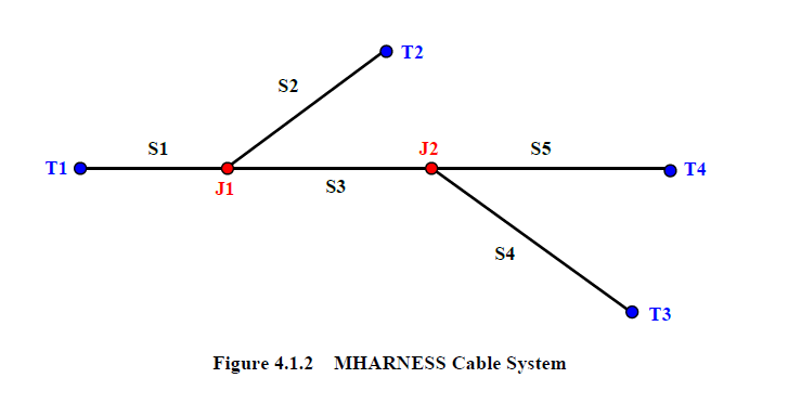
A system with five segments, labeled S1 through S5; two junctions, J1 and J2, and four terminations, T1 through T4 is shown in Figure 4.1.2. A junction always exists at a voltage node (see Figure 3.2.1). A termination is where a segment terminates with a specified boundary condition or a connector conductance. This boundary condition consists of one of the eight allowable circuit terminations. There is no interaction between segments except for the conservation of charge at the junction.
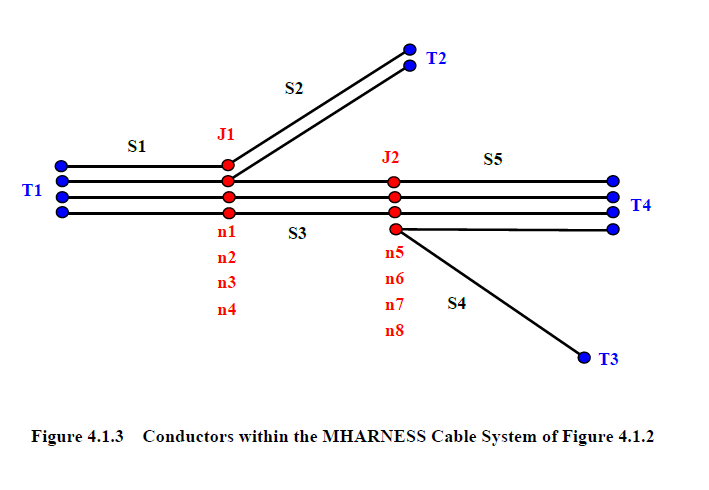
For a multi-branched system, the conductors within a segment constituting one of the branches are properly joined by utilizing nodes at the junction. The individual conductors of the cable system seen in Figure 4.1.2 are depicted in Figure 4.1.3. There are four conductors within segment S1, two conductors in segment S2, three conductors in S3, one conductor in S4, and four conductors in S5.
There are four nodes in junction J1. These nodes are specified as n1 through n4. A conductor in segment S1 is connected to a conductor in S2 at node n1. Another conductor in S1, a conductor in S2, and a conductor in S3 are all connected at node n2. Two conductors in S1 are connected to two other conductors in S3 at nodes n3 and n4. There are also four nodes in junction J2. These nodes are specified as n5 through n8. Three conductors in S3 are connected to three other conductors in S5 at nodes n5, n6, and n7. A conductor in S4 is connected to a conductor in S5 at node n8. Any conductor from a segment entering a junction is connected to one and only one node. Conductors of the same segment can be connected to the same node. This can be used to simulate a return path.
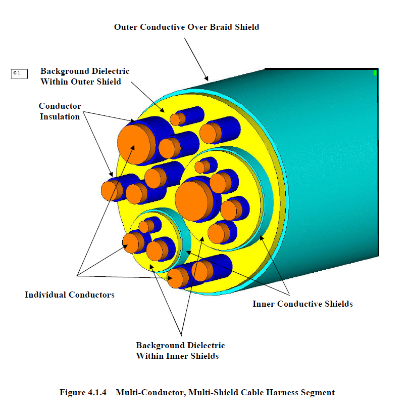
Cable segments consisting of individual conductors were shown in Figure 4.1.3. Cable segments can also have shields. A multi-conductor, multi-shield cable segment is shown in Figure 4.1.4. This particular cable segment contains 20 conductors.
• 1 Overbraid
• 2 Inner shields
• 17 individual wires
Within one of the inner shields are five wires and within the other are three.
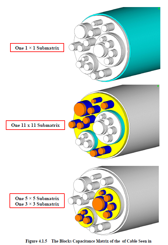
The interaction of conductors within a segment is accomplished using impedance matrices (capacitance, inductance, and conductance). The capacitance matrix associated with the segment in Figure 4.1.4 would be square with a dimension of 20. However, interaction through shields of various kinds can be complex requiring constant matrix development and inversions throughout the entire simulation. To circumvent this difficulty, the interactions through shields is accomplished using a shield transfer impedance. As a result, the 20 × 20 capacitance matrix can be written in block diagonal form consisting of:
• One 1 × 1 block matrix
• One 11 × 11 block matrix
• One 5 × 5 block matrix
• One 3 × 3 block matrix
The conductors associated with these block matrices are shown in Figure 4.1.5. An alternative approach is to separate out the various blocks and identify these as separate segments with interactions defined using shield transfer impedances. This is the approach used in MHARNESS. The cable of Figure 4.1.4 must therefore be defined as four separate segments.
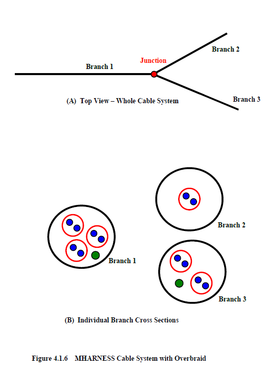
An example of an MHARNESS cable system is shown in Figure 4.1.6. A top view of the whole system is shown in Figure 4.1.6(A). This system consists of three branches. A cross-section of each branch is shown in Figure 4.1.6(B). This system thus consists of three shielded twisted wire pairs and another wire in Branch 1, one shielded twisted pair in Branch 2, and two shielded twisted pairs along with another wire in Branch 3.
The overbraid conductor of each branch within the cable of Figure 4.1.6 constitutes three separate segments, S21, S22, S23 each containing 1 conductor, as shown in Figure 4.1.7(A). These conductors are joined at node n21 in junction J1. Since there is one conductor in each segment the line impedance matrices consist of single coefficients.
The shields of the twisted pairs and the one other wire constitute Segment S11, as shown in Figure 4.1.7(B). Segment S11 contains four conductors, segment S12 contains 1 conductor, and segment S13 contains 3 conductors. There is one junction containing 4 nodes. These nodes are labeled, n11, n12, n13, n14. The line impedances consist of full 4x4 matrices for segment S11, single coefficients for segment S12, and full 3x3 matrices for segment S13, as shown in Figure 4.1.7(B). The last set of segments are shown in Figure 4.1.7(C).
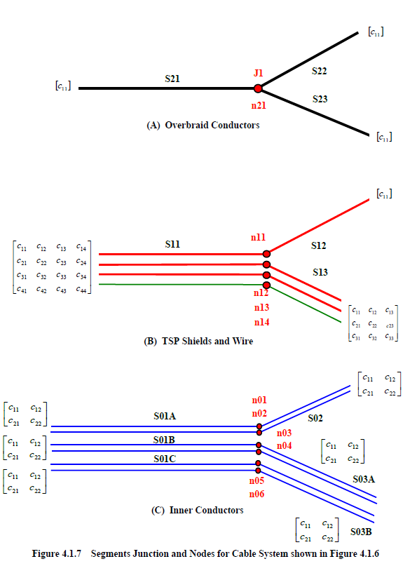
The cable system of Figure 4.1.7 thus consists of three shielding levels. The outer level has 3 segments (Figure 4.1.7(A)), the next shielding level also has 3 segments (Figure 4.1.7(B), and the last shielding level has 6 segments.
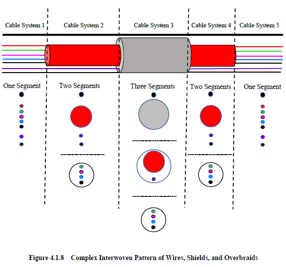
The examples given above all portrayed cable systems with segments containing conductors that were defined at the same shielding level throughout the entire system. These systems consisted of conductors at an inner level, at the next shielding level, and at still another higher shielding level. However, conductors at one shielding level in a particular segment do not have to stay at the same respective level in another connecting segment. A more complex cable system is portrayed in Figure 4.1.8 below. In this system, shields in a segment that contain inner conductors of one cable system may become conductors grouped with those same inherent inner conductors in another system. For example, the red conductor of cable system 1 becomes a shield in cable system 2. The thick black conductor of cable system 1 becomes an overbraid in cable system 3.
EMA3D - © 2026 EMA, Inc. Unauthorized use, distribution, or duplication is prohibited.