Coordinate System |
A three-dimensional coordinate system is inherent within the algorithms of
MHARNESS®. However, this coordinate system is relevant only under the following four situations.1) Plane wave illumination
2) Automatic impedance matrix computations
3) Radiated field output
4) When MHARNESS employed within EMA3D
If a plane wave is specified, then the geometric relationship between the aspects of the plane wave (incident direction and electric field polarization) and the orientation of the cable conductors is important. In addition, if a ground reference is desired, then the height of the cable system above the ground plane is required.
If automatic computation of the impedance matrices is specified, then a detailed description of the cable cross-sectional geometry along with the geometric relation to the reference conductor (e.g. height above ground plane) is required. Important segment cross-sectional information includes the relative positions of the conductors, conductor radii, and dielectric jacket (insulation) radii.
If radiated fields are desired for output, then the coordinate location of the radiated field needs to be defined.
If MHARNESS is employed within EMA3D, then an appropriate reference is automatically computed by the algorithms of EMA3D and therefore the geometric information pertaining to the cable cross-section is necessary for each cable segment within the EMA3D problem space.
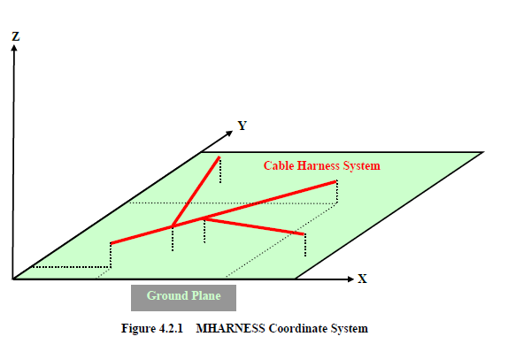
The four situations discussed above require a coordinate system for proper definition. The coordinate system of MHARNESS assumes that the cable harness system exists on an xy plane, as depicted in Figure 4.2.1, although various portions of the cable system may exist at different heights. If a ground plane reference exists, then it is located on the xy coordinate plane at the z-coordinate of, z = 0.0, and the cable harness system must be above the ground plane (z > 0.0).
EMA3D - © 2026 EMA, Inc. Unauthorized use, distribution, or duplication is prohibited.