Segment |
An
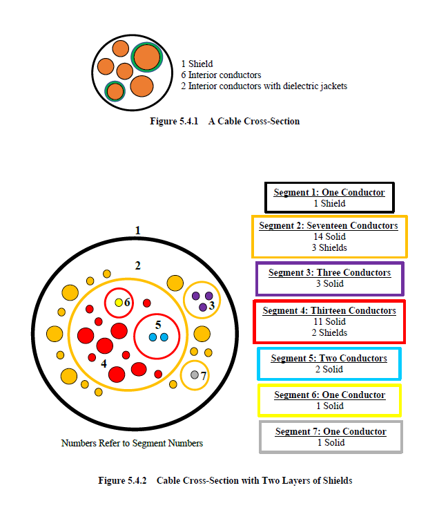
MHARNESS® cable segment is a set of parallel conductors, each possessing a constant cylindrical cross-section and a constant inter-conductor geometric relationship throughout the length of the segment. The inherent conductors interact through impedance matrices (capacitance, inductance, and conductance). A dielectric jacket may be defined on any conductor within the segment. A picture of a cable segment cross-section is provided in Figure 5.4.1. In this figure there is one shield and six interior conductors. Two of the interior conductors possess a dielectric jacket. Since each segment is defined with a constant cross-section throughout the entire length, then each shield and each conductor/dielectric jacket constituting the segment must possess the same length.Each conductor/jacket within the segment is considered solid to effect proper electromagnetic interaction between the various conductors within the segment. This interaction is implemented using impedance matrices. This solid nature pertains only to the immediate segment. Other segments may be defined within a conductor. In these cases, the conductor with an interior segment specified becomes, by definition, a cable shield. A drawing of a cable cross-section is provided in Figure 5.4.2. The cable within this figure contains 38 conductors of which 32 are solid and 6 are shields. There is no limit to the number of embedded conductors and shields.
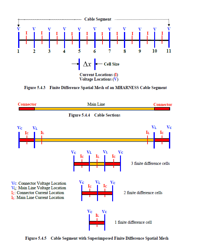
The MHARNESS program is a transmission line solver based upon the finite difference time domain technique (See Chapter 3). There is thus an associated finite difference space step and a finite difference time step. Each cable segment is therefore assigned a finite difference space step (or cell size) as seen in Figure 5.4.3. The cable in the figure is 10 finite difference cells long. The cable finite difference cells are indexed 1 through 11. Cable voltages lie at whole integral index locations and the currents lie at half-integral index locations. The conductor transmission line inductance is utilized at the current locations, while the capacitance and conductance are used at the voltage locations. For a cable consisting of 10 finite difference cells, there are 10 current locations and 11 voltage locations. When designating voltage output at the cable endpoints, the 1 and/or 11 voltage indices should be specified.
There are three sections associated with any conductor/dielectric jacket. These sections consist of the main segment line in addition to a connector on each end, as shown in Figure 5.4.4. The connector is defined by the last finite difference cell existing on each end of the segment. A connector may be defined with difference impedance definitions and different topologies (See Section 5.5) than that of the main line. This could significantly affect cable behavior. If connectors are not defined, then the end cells inherit the properties of the main line.
A finite difference mesh is superimposed on the three sections of a conductor in Figure 5.4.5. Inspection of this figure shows connector voltage locations, connector current locations, main line voltage locations, and main line current locations. For conductors consisting of any number of finite difference cells, a connector voltage always exists at both ends. However, for short conductors consisting of one or two cells, the distinction between the main line properties and those of the connectors needs to be understood.
If the conductor is only two cells long, as shown in the figure, then there are two current locations and three voltage locations. The two end voltages and the two end currents use connector parameters. The center voltage location uses main line parameters. For a conductor with a one cell length, there are two voltage locations and one current location. Again, the two voltage locations adopt connector parameters while the single current location adopts the main line parameters.
EMA3D - © 2026 EMA, Inc. Unauthorized use, distribution, or duplication is prohibited.