Junction and Node |
Cable junctions were introduced in Section 4.1. Cable junctions contain nodes to which segment conductors are connected. A cable system consisting of three segments is shown below in Figure 5.4.2.1. Segment S1 contains seven conductors, segment S2 contains 3 conductors, and segment S3 contains 4 conductors. There is one junction J1 containing 7 nodes. In this cable system all conductors within each segment terminate at a node in the junction. However, this need not be the case.
An alternative configuration is shown in Figure 5.4.2.2. In this figure two conductors in segment S1 terminate at a single node, one conductor of segment S1 terminates at a single node with no other connected conductors from any other segment, and one node contains a junction circuit termination. This circuit termination provides a current path to the cable reference. A circuit termination can be specified for any node in a junction. However, a junction circuit termination can only be specified when the terminating conductance matrix for all segments at the junction is zero or nonexistent. Any number of conductors from a single segment can terminate at a single node in a junction.
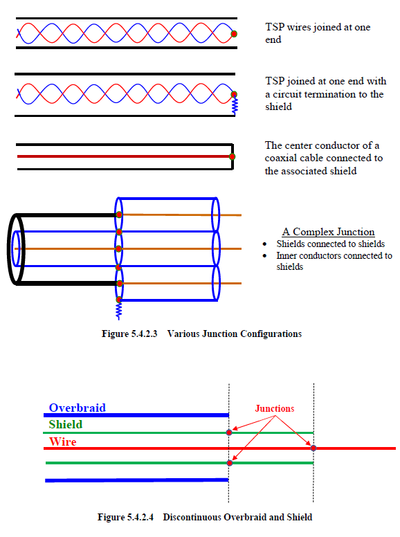
Nodes in a junction can be used to connect any conductors in a single segment or any conductors from multiple segments. Some junction configurations are provided in Figure 5.4.2.3.
An overbraid, cable shield, or a conductor does not have to be continuous in
MHARNESS® as illustrated in Figure 5.4.2.4. In this figure the overbraid and the shield are not continuous. The shield extends beyond the overbraid and the wire extends beyond the shield. A junction, however, is required on the shield at the termination of the overbraid location and on the wire at the termination of the shield location, as illustrated in the figure. This is because all MHARNESS segments must maintain a constant cross-section.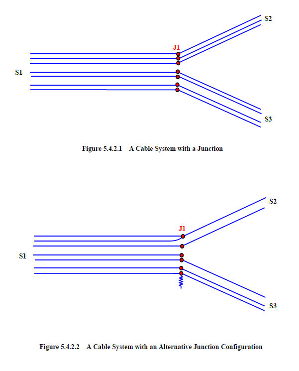
EMA3D - © 2026 EMA, Inc. Unauthorized use, distribution, or duplication is prohibited.